1.Select a new test position: Cue the test track corresponding to the center frequency of the dip. In the example in Figure 19 you would play Tracks 14 (52Hz) and 18 (40Hz). Press Play ›. You will see a reading very close to what you had before. Now slowly move the RSLM around the area, if possible remaining within about a foot of the original test point. As you move the RSLM, watch the bar graph. You will observe large level fluctuations. Find a location for the subwoofer or a test location that raises the response at these frequencies. You may find it helpful to move the RSLM vertically. Dips can be oriented in any axis. The position that restores the level to about that of the adjacent test points is your new test position.
2.Reset the test level: Return to the section “Setting the Subwoofer Test Level” on page 7. Perform the procedure as described.
3.Repeat the measurements: Now that you are familiar with the measurement process, you can go much faster by using Tracks
Your second measurement will no longer exhibit the deep response dips. However, the peak will still be evident. Without the influence of the response dips, the amplitude and center of the peak may have changed.
4.Interpret the new data: Compare your new data to the examples given in this section of the manual. Follow the instructions for the example that most closely matches your new measurement.
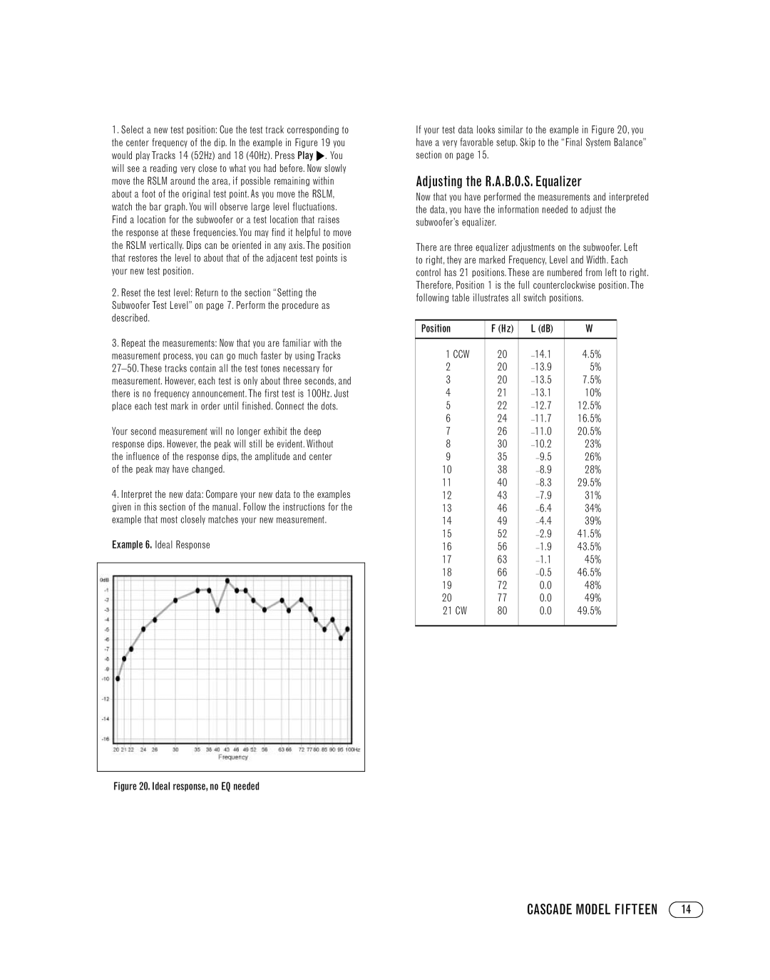
Example 6. Ideal Response
Figure 20. Ideal response, no EQ needed
If your test data looks similar to the example in Figure 20, you have a very favorable setup. Skip to the “Final System Balance” section on page 15.
Adjusting the R.A.B.O.S. Equalizer
Now that you have performed the measurements and interpreted the data, you have the information needed to adjust the subwoofer’s equalizer.
There are three equalizer adjustments on the subwoofer. Left to right, they are marked Frequency, Level and Width. Each control has 21 positions. These are numbered from left to right. Therefore, Position 1 is the full counterclockwise position. The following table illustrates all switch positions.
Position | F (Hz) | L (dB) | W |
|
|
|
|
1 CCW | 20 | 4.5% | |
2 | 20 | 5% | |
3 | 20 | 7.5% | |
4 | 21 | 10% | |
5 | 22 | 12.5% | |
6 | 24 | 16.5% | |
7 | 26 | 20.5% | |
8 | 30 | 23% | |
9 | 35 | 26% | |
10 | 38 | 28% | |
11 | 40 | 29.5% | |
12 | 43 | 31% | |
13 | 46 | 34% | |
14 | 49 | 39% | |
15 | 52 | 41.5% | |
16 | 56 | 43.5% | |
17 | 63 | 45% | |
18 | 66 | 46.5% | |
19 | 72 | 0.0 | 48% |
20 | 77 | 0.0 | 49% |
21 CW | 80 | 0.0 | 49.5% |
|
|
|
|
CASCADE MODEL FIFTEEN | 14 |
