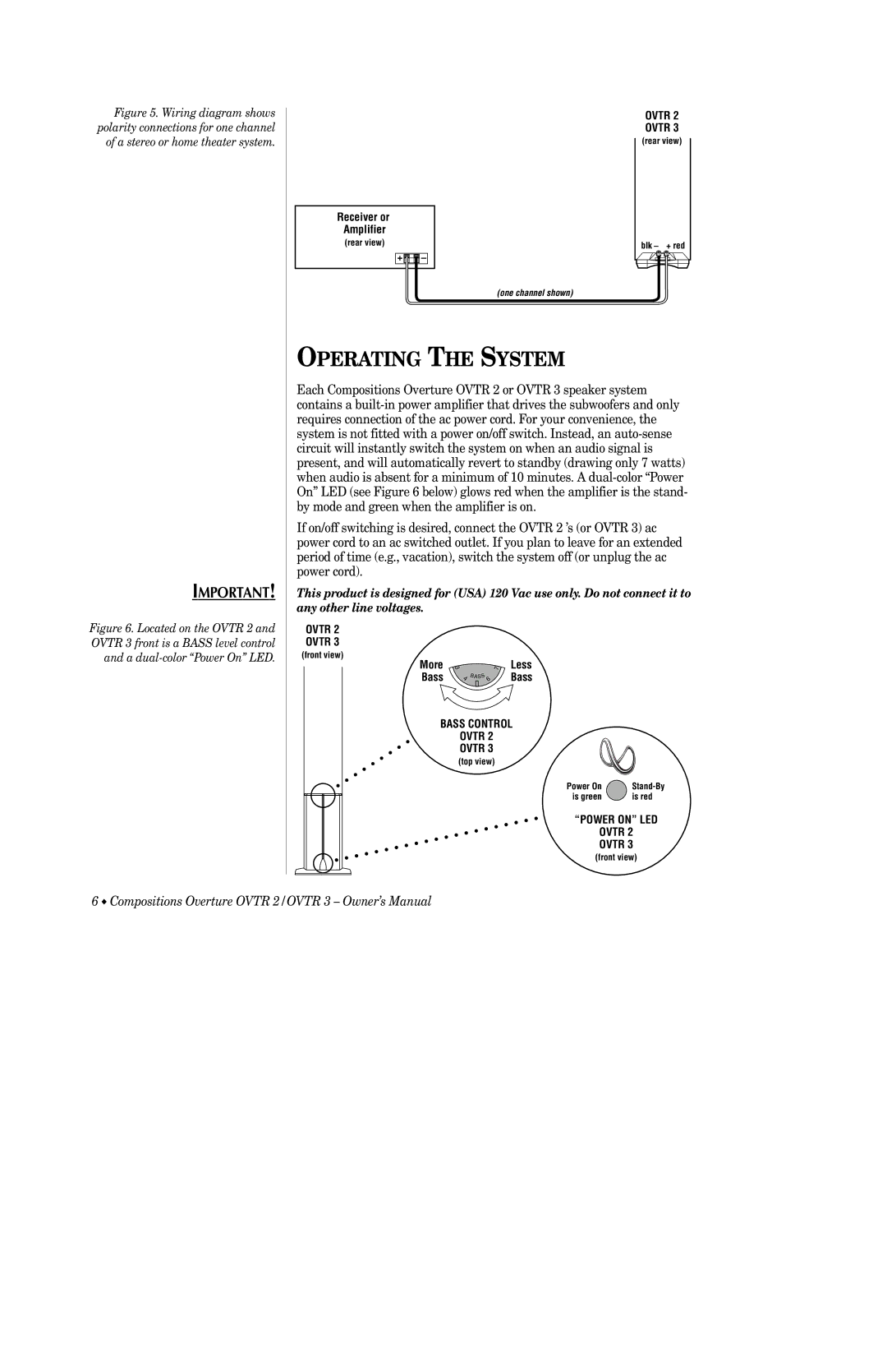
Figure 5. Wiring diagram shows polarity connections for one channel of a stereo or home theater system.
Receiver or
Amplifier
(rear view)
+ | – |
OVTR 2
OVTR 3
(rear view)
blk – + red
(one channel shown)
IMPORTANT!
Figure 6. Located on the OVTR 2 and OVTR 3 front is a BASS level control and a dual-color “Power On” LED.
OPERATING THE SYSTEM
Each Compositions Overture OVTR 2 or OVTR 3 speaker system contains a
If on/off switching is desired, connect the OVTR 2 ’s (or OVTR 3) ac power cord to an ac switched outlet. If you plan to leave for an extended period of time (e.g., vacation), switch the system off (or unplug the ac power cord).
This product is designed for (USA) 120 Vac use only. Do not connect it to any other line voltages.
OVTR 2
OVTR 3
(front view)
More | 3 | 7 | Less |
Bass | 4 | 6 | Bass |
|
| BASS |
|
BASS CONTROL
OVTR 2
OVTR 3
(top view)
Power On | |
is green | is red |
“POWER ON” LED
OVTR 2
OVTR 3
(front view)
6 ◆ Compositions Overture OVTR 2/OVTR 3 – Owner’s Manual