Viewing the Connecting Panel
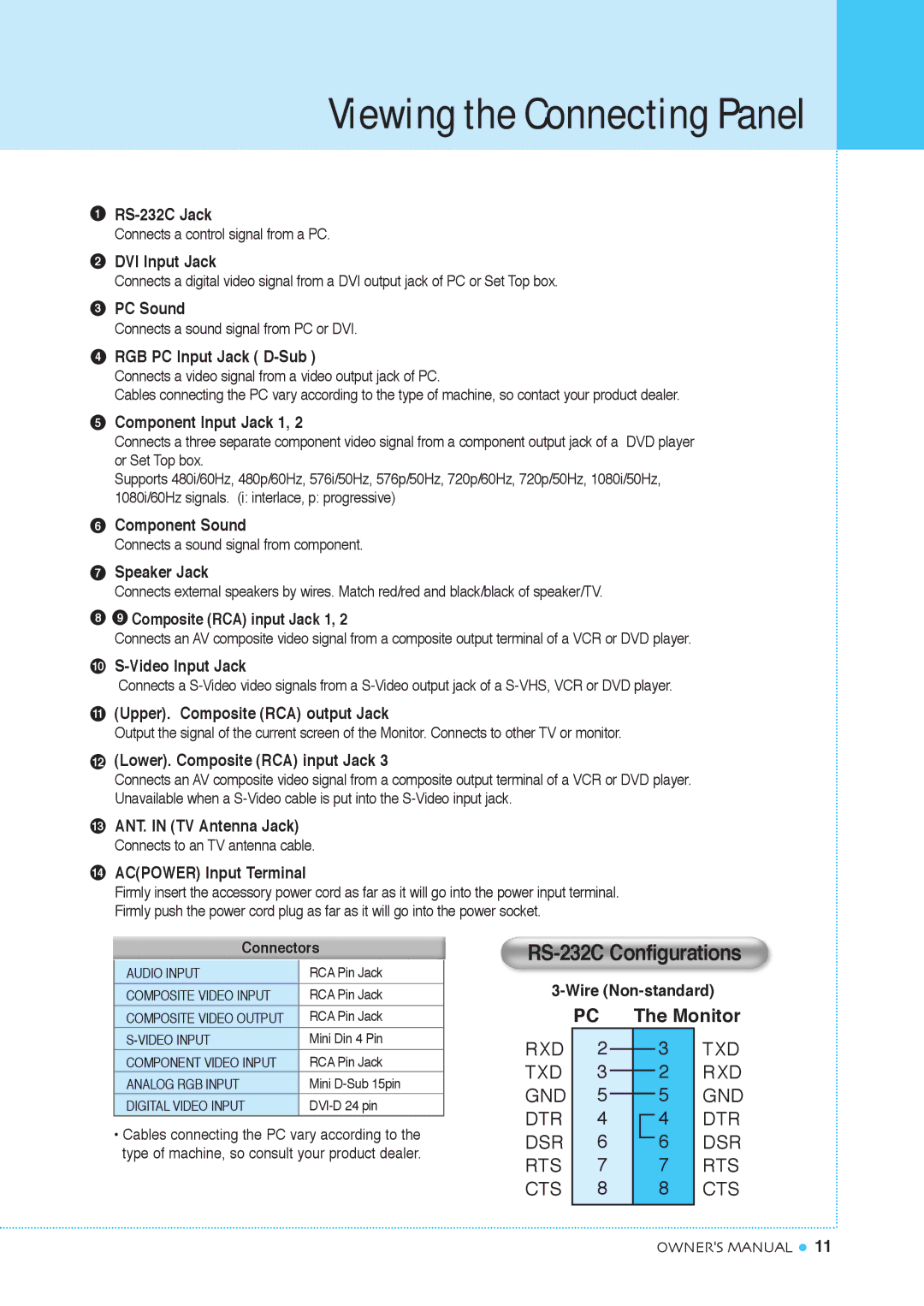
1
Connects a control signal from a PC.
2DVI Input Jack
Connects a digital video signal from a DVI output jack of PC or Set Top box.
3PC Sound
Connects a sound signal from PC or DVI.
4RGB PC Input Jack ( D-Sub )
Connects a video signal from a video output jack of PC.
Cables connecting the PC vary according to the type of machine, so contact your product dealer.
5Component Input Jack 1, 2
Connects a three separate component video signal from a component output jack of a DVD player or Set Top box.
Supports 480i/60Hz, 480p/60Hz, 576i/50Hz, 576p/50Hz, 720p/60Hz, 720p/50Hz, 1080i/50Hz, 1080i/60Hz signals. (i: interlace, p: progressive)
6Component Sound
Connects a sound signal from component.
7Speaker Jack
Connects external speakers by wires. Match red/red and black/black of speaker/TV.
89 Composite (RCA) input Jack 1, 2
Connects an AV composite video signal from a composite output terminal of a VCR or DVD player.
10
Connects a
11(Upper). Composite (RCA) output Jack
Output the signal of the current screen of the Monitor. Connects to other TV or monitor.
12(Lower). Composite (RCA) input Jack 3
Connects an AV composite video signal from a composite output terminal of a VCR or DVD player. Unavailable when a
13ANT. IN (TV Antenna Jack) Connects to an TV antenna cable.
14AC(POWER) Input Terminal
Firmly insert the accessory power cord as far as it will go into the power input terminal. Firmly push the power cord plug as far as it will go into the power socket.
Connectors
AUDIO INPUT | RCA Pin Jack |
COMPOSITE VIDEO INPUT | RCA Pin Jack |
COMPOSITE VIDEO OUTPUT | RCA Pin Jack |
Mini Din 4 Pin | |
COMPONENT VIDEO INPUT | RCA Pin Jack |
ANALOG RGB INPUT | Mini |
DIGITAL VIDEO INPUT |
•Cables connecting the PC vary according to the type of machine, so consult your product dealer.
RS-232C Configurations
| PC | The Monitor | |||||
RXD | 2 |
|
|
|
| 3 | TXD |
|
|
|
| ||||
TXD | 3 |
|
|
|
| 2 | RXD |
|
|
|
| ||||
GND | 5 |
|
|
|
| 5 | GND |
|
|
|
| ||||
DTR | 4 |
|
|
| 4 | DTR | |
|
| ||||||
DSR | 6 |
|
|
| 6 | DSR | |
|
| ||||||
RTS | 7 |
| 7 | RTS | |||
CTS | 8 |
| 8 | CTS | |||
|
|
|
|
|
|
|
|
OWNER'S MANUAL ![]() 11
11
