MAINTENANCE SECTION
ASSEMBLY
General Instructions
1.Always press on the inner ring of a
2.Always press on the outer ring of a
3.Whenever grasping a tool or part in a vise, always use
4.Always clean every part and wipe every part with a thin film of oil before installation.
5.Check every bearing for roughness. If an open bearing must be cleaned, wash it thoroughly in clean solution and dry with a clean cloth. Sealed or shielded bearings should not be cleaned. Work grease into every open bearing before installation.
6.Apply a film of
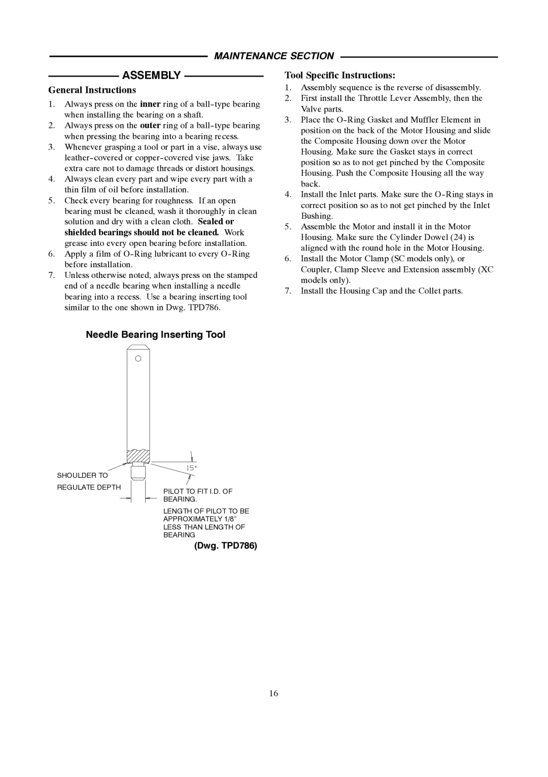
7.Unless otherwise noted, always press on the stamped end of a needle bearing when installing a needle bearing into a recess. Use a bearing inserting tool similar to the one shown in Dwg. TPD786.
Tool Specific Instructions:
1.Assembly sequence is the reverse of disassembly.
2.First install the Throttle Lever Assembly, then the Valve parts.
3.Place the
4.Install the Inlet parts. Make sure the
5.Assemble the Motor and install it in the Motor Housing. Make sure the Cylinder Dowel (24) is aligned with the round hole in the Motor Housing.
6.Install the Motor Clamp (SC models only), or Coupler, Clamp Sleeve and Extension assembly (XC models only).
7.Install the Housing Cap and the Collet parts.
Needle Bearing Inserting Tool
SHOULDER TO REGULATE DEPTH
PILOT TO FIT I.D. OF BEARING.
LENGTH OF PILOT TO BE APPROXIMATELY 1/8”
LESS THAN LENGTH OF BEARING
(Dwg. TPD786)
16