OPERATING INSTRUCTIONS
Refer to pages 4 and 5 for parts reference.
To INCREASE outlet pressure, turn the (6) adjusting screw CLOCKWISE (see figure 3).
To DECREASE outlet pressure, turn the (6) adjusting screw COUNTERCLOCKWISE (see figure 3).
NOTE: Part
FLUSH-OUT FEATURE FOR DOWNSTREAM MODELS ONLY. See figure 4.
Flush the regulator periodically. The interval may vary de- pending on the amount and type of material used.
By using a wrench and
NOTE: The
FLUSH-OUT PROCEDURE
1.Remove spray gun or dispensing device, this will allow any particles to clear from the system.
2.Insert (21)
3.Turn up to two turns maximum. This will allow the ball to unseat and pass material at free flow (unregulated). DO NOT attempt to turn further to avoid damage.
4.Turn the plug back to its original position.
SEAT PLUG FEATURE
The (47) plug, located at the base of the regulator, can be removed for access to the ball and seat assembly for clean- ing and inspection for wear. With this feature, the regulator does not have to be unthreaded from the pumping system. Be certain to relieve system pressure (See “WARNING: DISAS- SEMBLY HAZARD”).
MAINTENANCE
Disassembly should be done on a clean work bench and use clean cloths.
If replacement parts are necessary, refer to the parts list and drawings on pages 4 and 5.
Upon reassembly, lubricate parts and use Loctite where indicated. Follow the torque specifications as shown. Service kits are available, which include parts typically needed for an overhaul.
Keep good records of service activity and include the regulator in a preventive maintenance program.
Certain “Smart Parts” are indicated with a “ ” in the parts list, these parts should be available for fast repair and re- duction of down time.
View of Spring | View of |
Adjustment Procedure. |
|
Figure 3 | Figure 4 |
TROUBLE SHOOTING
No fluid pressure.
Check for damaged or worn diaphragms.
Look for possible obstruction by hardened material or foreign matter, periodically use the regulator
Pressure creeps above the setting when system is dead ended and in a static (no flow) mode.
Check for dirty seat and clean as appropriate.
Check for worn or damaged seat and replace if necessary.
Outlet pressure drops below setting.
Check pump for proper operation and check for possible leakage problems.
Look for a clogged supply line problem, flush the supply line.
Fluid leakage from spring housing.
Check the bonnet
Check for damaged diaphragm, replace as needed.
Regulator will not function, even when dispens- ing device is opened.
Check for possible obstruction in the fluid line.
Inlet pressure is too high, causing a
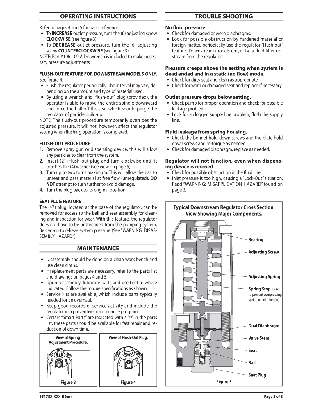
Typical Downstream Regulator Cross Section |
View Showing Major Components. |
Bearing |
Adjusting Screw |
Adjusting Spring |
Spring Stop (used |
to prevent compressing |
spring to solid height) |
Dual Diaphragm |
Valve Stem |
Seat |
Ball |
Seat Plug |
Figure 5 |
Page 3 of 8 |