DISASSEMBLY / REASSEMBLY
block, making sure it rests squarely on the (22) head plate.
40.Snug up the other four (26) cap screws in the top of the
(30)block manifold just enough to draw the (30) block manifold against the (22) head plate.
41.Tighten the four (26) cap screws which secure the (27) block to the (30) block manifold. Now, tighten the four
(26)cap screws in the top of the (30) block manifold.
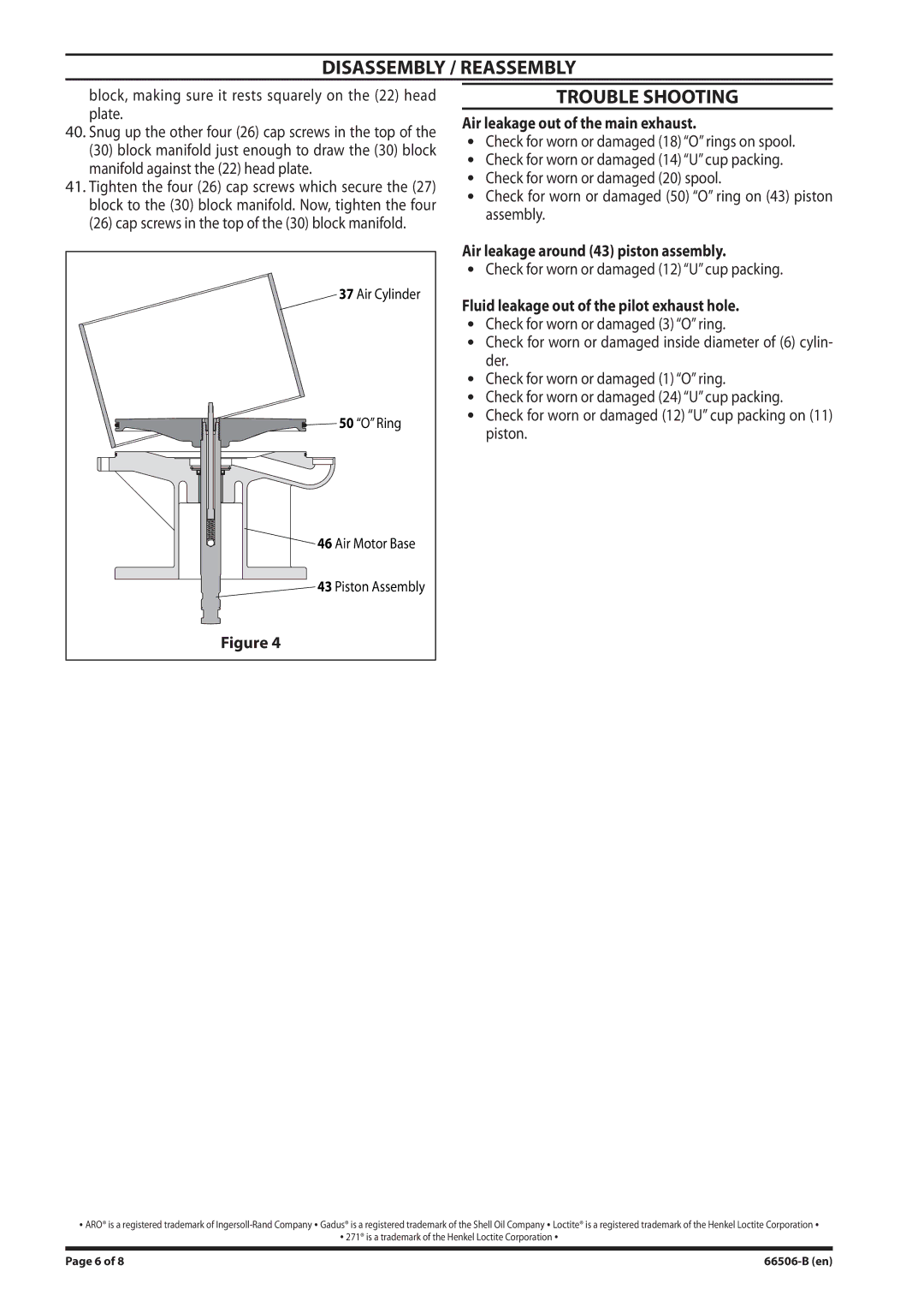
37 Air Cylinder
![]()
![]()
![]() 50 “O” Ring
50 “O” Ring
![]() 46 Air Motor Base
46 Air Motor Base
43 Piston Assembly
TROUBLE SHOOTING
Air leakage out of the main exhaust.
yCheck for worn or damaged (18) “O” rings on spool.
yCheck for worn or damaged (14) “U” cup packing.
yCheck for worn or damaged (20) spool.
yCheck for worn or damaged (50) “O” ring on (43) piston assembly.
Air leakage around (43) piston assembly.
yCheck for worn or damaged (12) “U” cup packing.
Fluid leakage out of the pilot exhaust hole.
yCheck for worn or damaged (3) “O” ring.
yCheck for worn or damaged inside diameter of (6) cylin- der.
yCheck for worn or damaged (1) “O” ring.
yCheck for worn or damaged (24) “U” cup packing.
yCheck for worn or damaged (12) “U” cup packing on (11) piston.
Figure 4
y ARO® is a registered trademark of
y 271® is a trademark of the Henkel Loctite Corporation y
Page 6 of 8 |