SELECTINGA LOCATION
GENERAL° Select a clean, dry,
TEMPERATURE.. Ideal operating temperatures are between 32"F and 100°F (0°C and 37.B_C) If temperatures consistently drop below 32°F (0"C), locale the unit inside a heated building !f th_s is not possible, you must protect safety!relief valves and drain valves from freezing
CAUTION Never operate in temperatures below 20°F (_6.6°C) or above 125°F (5t.0°C)..
HUMID AREAS. In frequently humid areas, moisture may form in the bare pump and produce sfudge in the lubricant, causing running
_ WARNING
,_.WARNING
z_ CAUTION
Do net use plastic pipe, rubber hose, or lead4in soldered joints anywhere in the compressed air system
If an afteroeoler, check valve, block vafve, er any other restriction is added to the compressor discharge, install a properly*sized ASME approved safetytrelief valve between the compressor discharge and the restriction.
If you will be using
1
parts to wear out prematurely Excessive moisture is especially likely to occur if the unit is located in an unheated area that is subject to large temperature changes Two signs of excessive humidity are external condensation on the bare pump when it cools down and a "_mllky_ appearance in petroleum compressor lubricant You may be able to prevent moisture from forming in the bare pump by increasing ventilation, operating for longer intervals or installing a crankcase heater kit
NOISE CONSIDERATIONS Consull local officials [or information regarding acceptable noise levels in your area To reduce excessive noise, use vibralion isolator pads or intake silencers, relocate the unit or construct total enclosures or baffle waits
PERMANENT MOUNTING
WARNING Remove the unit from the skid before mounting..
The unit must be permanently mounted When mounting the unit. bait the feet to a firm. fevel foundation (such as a concrete floor) Do not bolt uneven feet tight}y to the foundation, as this will cause excessive stress on the receiver tank Use metal shims under the "short" feet if necessary
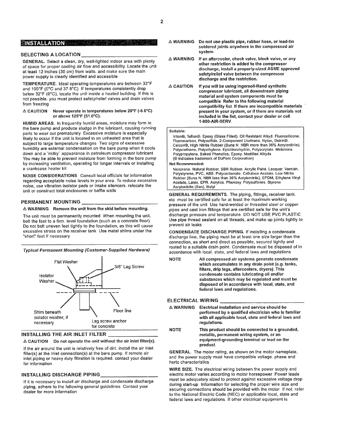
Typical Permanent Mounting (Customer.Supplied Hardware)
Fiat Washer
3/8" Lag Screw
Isofator
\
Shlm beneath | Floor Jlne |
isotater washer, if
necessaryLag screw anchor for concrete
INSTALLING THE A!R INLET FILTER
CAUTION Do not operate the unit without the air inlet filter(s).
If the air around the unit is relatively free of dirt, instant the air inter filter(s) at the inlet conneclion(s) at the bare pump. If remote air inlet piping or heavy duty filtration is required, contact your dealer for information
INSTALLING DISCHARGE PIPING
If it is necessary to install air discharge and condensate discharge
piping, adhere to the following genera{ guidelines Conlact your dee]or for more _nformation
Suitable:
Viton®, Teflon@',Epoxy (Glass Fltied), O_1Resistant A_kyd, Fluorostllcone. Fluorocarbon, Polysulflde,
Polyurethane, Polyethylene, Eplchtorohydrn, Polyac_late. Melamine. Potyprepylene, Baked PhenoIIce. Epoxy. Modified Alkyds
{® indicates trademark of DuPont Corporation)
Not Recommended:
Neoprene, Naturai Rubber, SBR Rubber. Acrylic Paint. Lacquer, Varnish. Polystyrene, PVC, ABS. Poiycarbenate. Cellulos_ Acetate, Low Nttrtle Rubber (Buna N. NBR less than 36% Actylonttdle), EPDM, Ethylene Vinyl Acetate, Latex. EPR. Acrylics, Phenoxy Polysalfones. Styrene Aorylenitrlte (San), Butyl
GENERAL REQUIREMENTS.. The piping, fittings, receiver tank. etc must be certified safe for at least Ihe maximum working pressure of the unit Use
CONDENSATE DISCHARGE PIPING If inslalltng a condensate discharge line, the piping must be at Ieast one size larger than the connection, as short and direct as possible, secured tighBy and routed to a suitable drain point Condensate must be disposed of in accordance wffh local, state, and federal laws and regulations
NOTEAll compressed air systems generate condensate which accumulates In any drain point (e.go tanks, filters, drip legs, affercoolers, dryers). This condensate contains lubricating oil and/or substances which may be regulated and must be disposed of in accordance with local, state, and federal laws and regulations..
ELECTRICAL WIRING
_, WARNING Electrical installation and service shoutd be
performed by a qualified electrician who is familiar with all applicable loca!, state and federal laws and regu}attons r
NOTEThis product should be connected to a grounded, metallic, permanent wiring system, or an
product.
GENERAL The motor rating, as shown on the motor nameplate, and the power supply must have compatible voltage, phase and hertz characleristics
WIRE SIZE. The electrical wiring between the power supply and electric motor varies according to motor horsepower Power leads must be adequately sized to protect against excessive voltage drop during