Manuals
/
Ingersoll-Rand
/
TV and Video
/
Universal Remote
Ingersoll-Rand
TP0423S5XXXXXXXX Installation, Operating Instructions, Air Controls, To Lower Lift
Models:
TP0423S5XXXXXXXX
1
2
4
4
Download
4 pages
30.99 Kb
1
2
3
4
Install
Parts list
Model Description Chart
Dimension
Page 2
Image 2
Page 1
Page 3
Page 2
Image 2
Page 1
Page 3
Contents
MODEL DESCRIPTION CHART
READ THIS MANUAL CAREFULLY BEFORE INSTALLING
SERVICE KITS
INCLUDING OPERATION, INSTALLATION AND MAINTENANCE
OPERATING INSTRUCTIONS
INSTALLATION
WARNING STAND CLEAR WHEN RAISING OR LOWERING THE LIFT
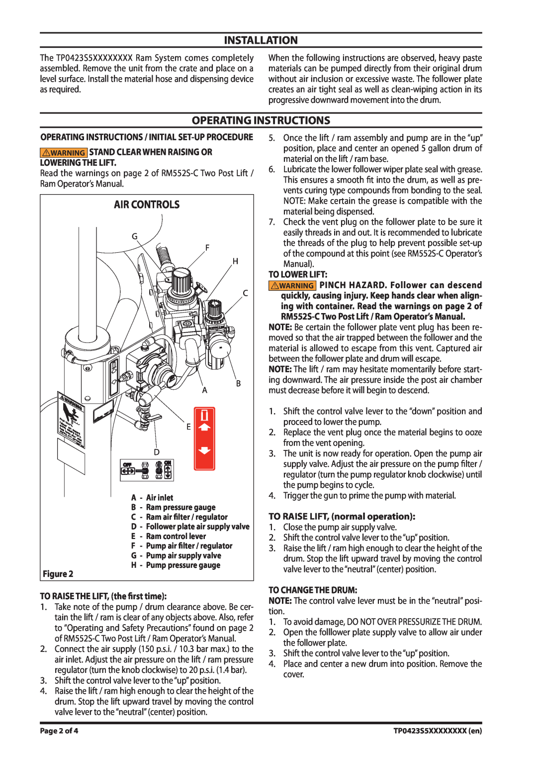
AIR CONTROLS
PARTS LIST / TP0423S5XXXXXXXX
22.000”
DIMENSIONAL DATA
24.000”
1.000”
Top
Page
Image
Contents