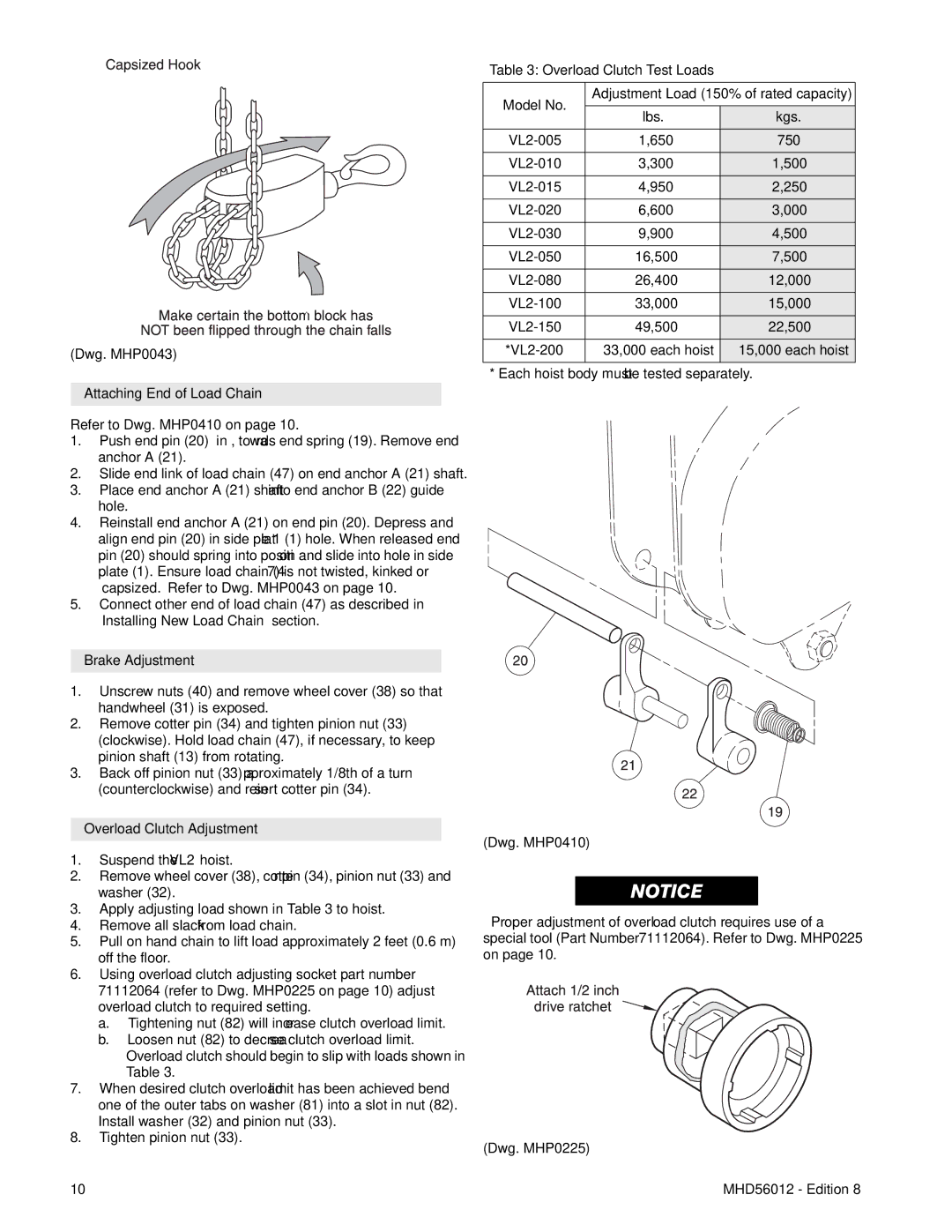
(Dwg. MHP0043)
Attaching End of Load Chain
Refer to Dwg. MHP0410 on page 10.
1.Push end pin (20) “in”, towards end spring (19). Remove end anchor A (21).
2.Slide end link of load chain (47) on end anchor A (21) shaft.
3.Place end anchor A (21) shaft into end anchor B (22) guide hole.
4.Reinstall end anchor A (21) on end pin (20). Depress and align end pin (20) in side plate 1 (1) hole. When released end pin (20) should spring into position and slide into hole in side plate (1). Ensure load chain (47) is not twisted, kinked or “capsized.” Refer to Dwg. MHP0043 on page 10.
5.Connect other end of load chain (47) as described in “Installing New Load Chain” section.
Brake Adjustment
1.Unscrew nuts (40) and remove wheel cover (38) so that handwheel (31) is exposed.
2.Remove cotter pin (34) and tighten pinion nut (33) (clockwise). Hold load chain (47), if necessary, to keep pinion shaft (13) from rotating.
3.Back off pinion nut (33) approximately 1/8th of a turn (counterclockwise) and reinsert cotter pin (34).
Overload Clutch Adjustment
1.Suspend the VL2 hoist.
2.Remove wheel cover (38), cotter pin (34), pinion nut (33) and washer (32).
3.Apply adjusting load shown in Table 3 to hoist.
4.Remove all slack from load chain.
5.Pull on hand chain to lift load approximately 2 feet (0.6 m) off the floor.
6.Using overload clutch adjusting socket part number 71112064 (refer to Dwg. MHP0225 on page 10) adjust overload clutch to required setting.
a.Tightening nut (82) will increase clutch overload limit.
b.Loosen nut (82) to decrease clutch overload limit. Overload clutch should begin to slip with loads shown in Table 3.
7.When desired clutch overload limit has been achieved bend one of the outer tabs on washer (81) into a slot in nut (82). Install washer (32) and pinion nut (33).
8.Tighten pinion nut (33).
10
Table 3: Overload Clutch Test Loads
Model No. | Adjustment Load (150% of rated capacity) | ||
|
| ||
lbs. | kgs. | ||
| |||
1,650 | 750 | ||
3,300 | 1,500 | ||
4,950 | 2,250 | ||
6,600 | 3,000 | ||
9,900 | 4,500 | ||
16,500 | 7,500 | ||
26,400 | 12,000 | ||
33,000 | 15,000 | ||
49,500 | 22,500 | ||
33,000 each hoist | 15,000 each hoist | ||
|
|
| |
* Each hoist body must be tested separately.
(Dwg. MHP0410)
•Proper adjustment of overload clutch requires use of a special tool (Part Number 71112064). Refer to Dwg. MHP0225 on page 10.
(Dwg. MHP0225)
MHD56012 - Edition 8