Electrical Connections
ELECTRIC SHOCK
•Turn off the electrical supply to the disposer before attempting any work on it. Use a voltmeter or circuit tester to ensure that power is off.
•All installation work must conform to local plumbing and electrical codes.
•All control centers and disposers must be carefully and permanently grounded.
•A properly fused disconnect must be installed at the electrical supply source for the control center.
ELECTRICAL CONNECTIONS
Connect the incoming line power and disposer motor to the labeled terminal block in the control center. Use appropriate voltage and phase electrical connection diagrams at the back of this manual. Wire the disposer motor for the correct voltage using the connection diagram inside the motor terminal box.
Make sure the solenoid valve is the same voltage as the control panel and supply power.
Connect water solenoid valve as shown in the wiring diagrams on pages 7, 8, 9, and 10.
Wire per local electrical code using 7/8" diameter holes in bottom of control center cabinet and install NEMA 4 watertight electrical connectors (not supplied).
After completing the connections, secure cover. Replace disposer motor cover.
TIME DELAY RELAY
(Optional, not supplied with MS)
The time delay relay may be used with the MS to delay solenoid valve
Ensure the voltage rating on the time delay relay and solenoid valve are the same as the disposer motor and line voltage.
PROPERTY DAMAGE
•Ensure that control center voltage and phase match the disposer motor and electrical supply. Check name plates on disposer and control centers for voltage and phase specifications.
•Refer to the control center wiring diagrams in this manual for correct connection.
•Use NEMA 4 watertight electrical connectors
(not supplied) when making electrical connections to the control center.
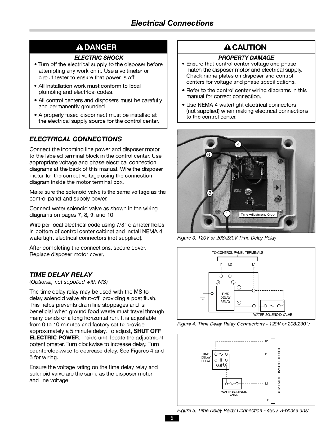
4
6
3
1Time Adjustment Knob
Figure 3. 120V or 208/230V Time Delay Relay
Figure 4. Time Delay Relay Connections - 120V or 208/230 V
Figure 5. Time Delay Relay Connection - 460V, 3-phase only
5