MS-5 Wiring Diagram
P/N 14356A
ELECTRICAL SHOCK
•Turn off the electrical supply to the disposer before attempting any work on it. Use a voltmeter or circuit tester to ensure that power is off.
•Installation must conform to local electrical codes.
•All control centers and disposers must be carefully and permanently grounded.
•A properly fused disconnect must be installed at the electrical supply source for the control center.
PROPERTY DAMAGE
•Ensure that the control center voltage and phase match the disposer motor and electrical supply. Check nameplates on disposers and control centers for voltage and phase specification.
•The disposer motor wiring connection is shown in the disposer terminal box.
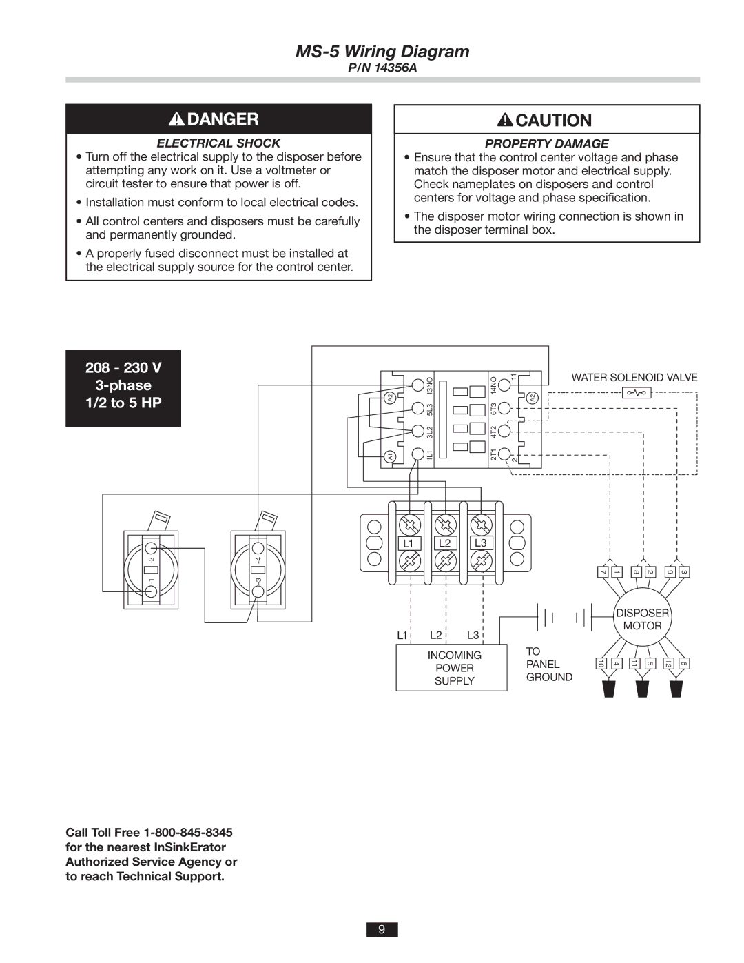
208 - 230 V
3-phase
1/2 to 5 HP
| 13NO | 14NO | 11 | WATER SOLENOID VALVE |
A2 | A2 | |||
| 5L3 | 6T3 |
|
|
| 3L2 | 4T2 |
|
|
A1 | 1L1 | 2T1 | 2 |
|
L1 | L2 |
L1 L2
L3
L3
7 | 1 | 8 | 2 | 9 | 3 |
DISPOSER
MOTOR
INCOMING
POWER
SUPPLY
TO PANEL GROUND
10
4
11
5
12
6
Call Toll Free
9