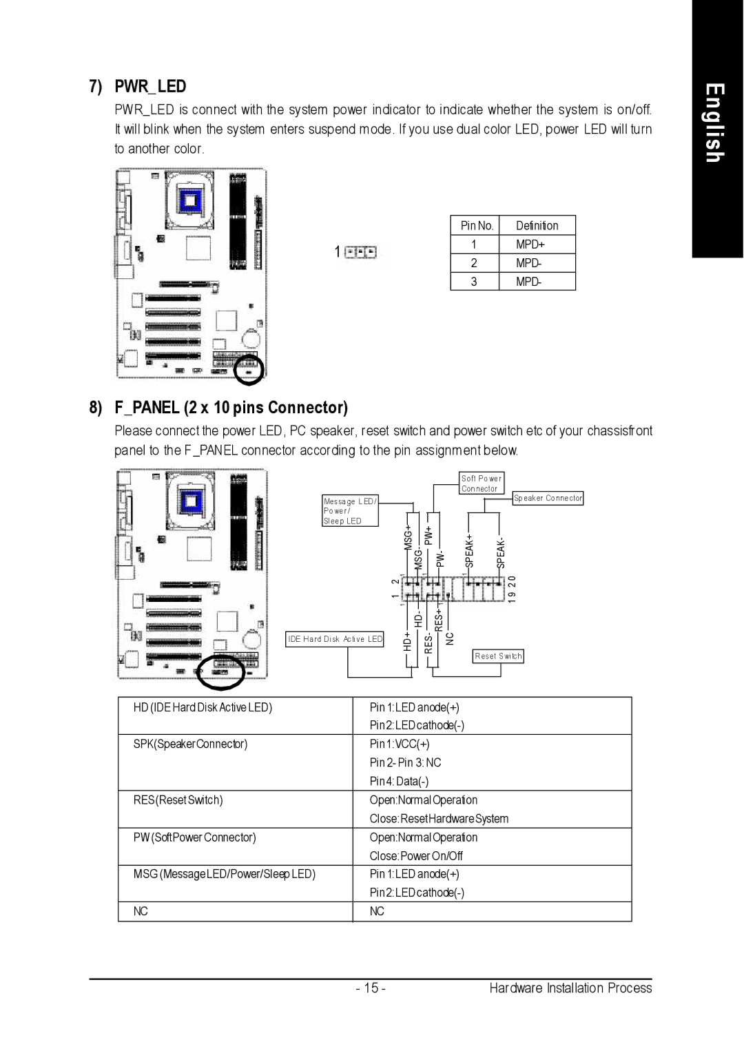
7) PWR_LED
PWR_ LED is connect with the system power indicator to indicate whether the system is on/off. It will blink when the system enters suspend mode . If you use dual color LED, power LED will turn to another color.
| Pin No. | Definition | |
1 | 1 | MPD+ | |
2 | MPD- | ||
| |||
|
|
| |
| 3 | MPD- |
English
8) F_PANEL (2 x 10 pins Connector)
Please connect the power LED, PC speaker, reset switch and power switch etc of your chassisfront panel to the F _PANEL connector according to the pin assignment below.
Messa ge L ED /
Po we r /
Sl ee p LED
IDE H a rd D i sk Acti ve LED
Soft Po we r
Con nector
![]()
![]() Sp eaker Co nne ctor
Sp eaker Co nne ctor
|
|
|
|
|
|
|
|
|
|
|
|
|
|
MSG+ |
| PW+ |
|
|
|
|
|
|
| ||||
|
|
|
| SPEAK+ | SPEAK- | ||||||||
MSG- |
| PW- |
| ||||||||||
|
|
|
| ||||||||||
2 1 |
|
| 1 |
|
|
|
| 1 |
|
|
| 0 | |
|
|
|
|
|
|
|
|
|
|
| 2 | ||
1 |
|
|
|
|
|
|
|
|
|
| 9 | ||
1 |
|
|
|
|
|
| 1 |
|
|
| 1 | ||
|
| HD- |
|
| RES+ |
|
|
|
|
|
| ||
H D + |
| RES- |
|
| N C |
|
|
| |||||
|
|
|
|
|
|
|
|
|
|
| R eset Swi tch | ||
|
|
|
|
|
|
|
|
|
|
|
|
|
|
HD (IDE Hard Disk Active LED) | Pin 1:LED anode(+) |
| Pin 2:LED |
|
|
SPK(SpeakerConnector) | Pin 1:VCC(+) |
| Pin 2- Pin 3: NC |
| Pin 4: |
|
|
RES(Reset Switch) | Open:Normal Operation |
| Close:ResetHardware System |
PW (SoftPower Connector) | Open:Normal Operation |
| Close:Power On/Off |
MSG (Message LED/Power/Sleep LED) | Pin 1:LED anode(+) |
| Pin 2:LED |
|
|
NC | NC |
|
|
- 15 - | Hardware Installation Process |