INSTALLATIONS
ATX Power ON Switch: Pins 5 and 13
This
| Pin # |
|
| Signal Name |
|
| 5 |
|
| PS_ON |
|
| 13 |
|
| Ground |
|
SMI/Hardware Switch: Pins 6 and 14
This connector supports the "Green Switch" on the control panel, which, when pressed, will force the system into the
| Pin # |
|
| Signal Name |
|
| 6 |
|
| SMI |
|
| 14 |
|
| Ground |
|
Reset Switch: Pins 7 and 15
The reset switch allows the user to reset the system without turning the main power switch off and then on again. Orientation is not required when making a connection to this header.
| Pin # |
|
| Signal Name |
|
| 7 |
|
| Reset# |
|
| 15 |
|
| Ground |
|
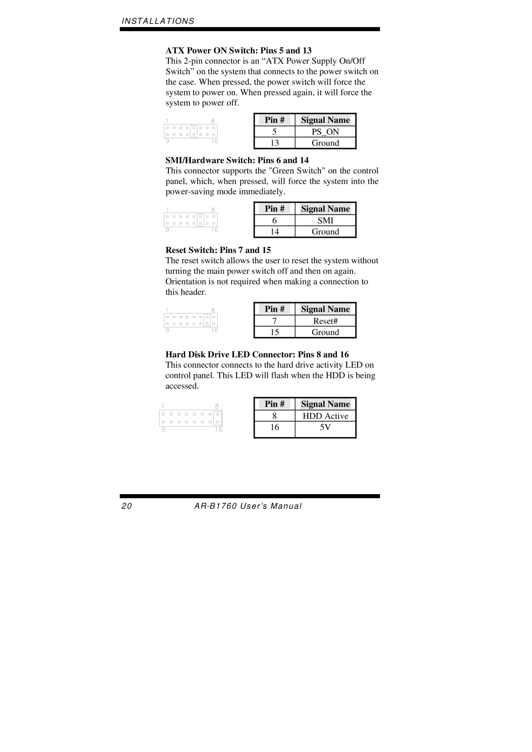
Hard Disk Drive LED Connector: Pins 8 and 16
This connector connects to the hard drive activity LED on control panel. This LED will flash when the HDD is being accessed.
| Pin # |
|
| Signal Name |
|
| 8 |
|
| HDD Active |
|
| 16 |
|
| 5V |
|
|
|
|
|
|
|
20 |