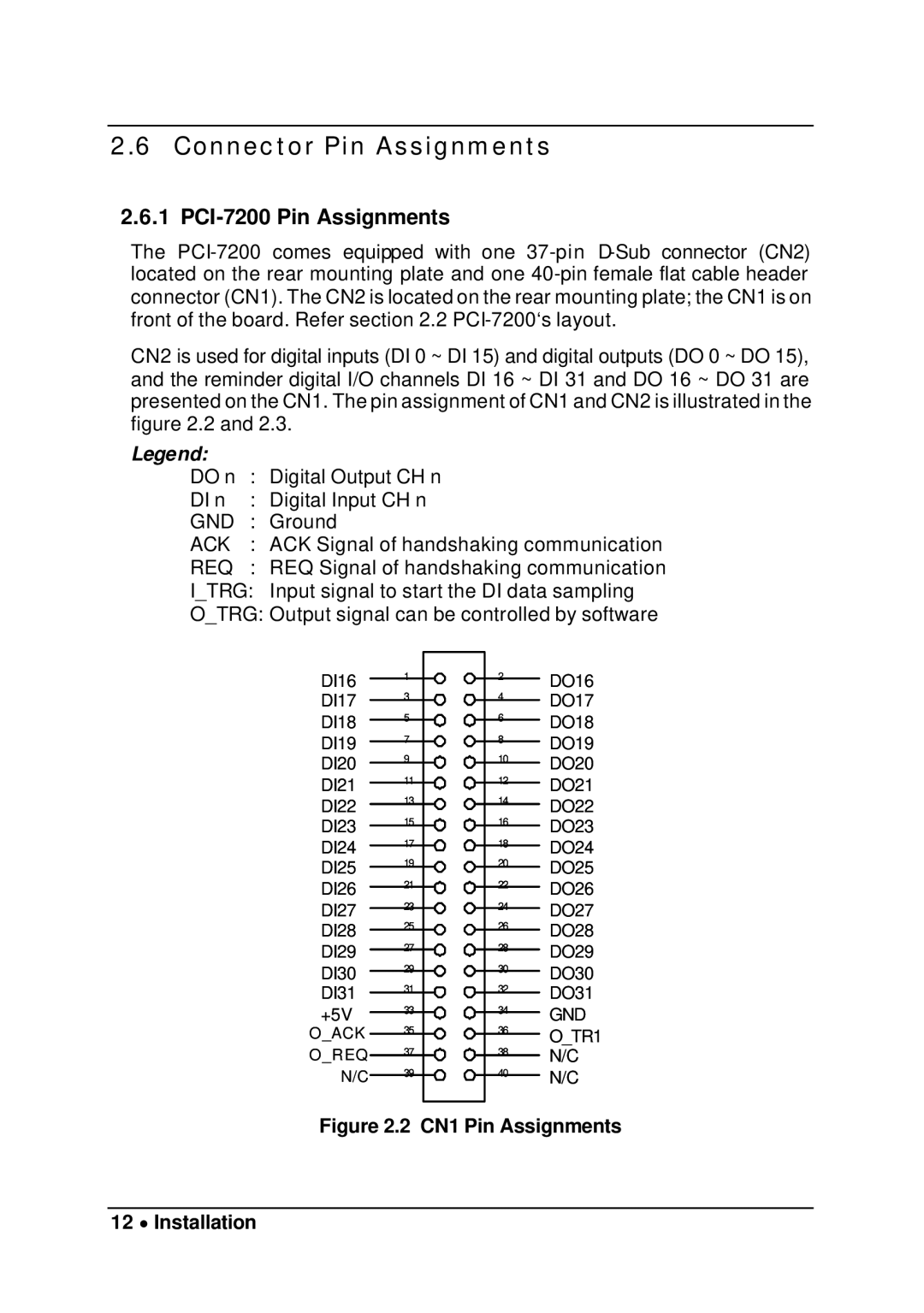
PCI-7200, cPCI-7200 specifications
The Intel cPCI-7200 is a high-performance, rugged computing platform designed to meet the demands of embedded and telecommunications applications. As a part of Intel’s CompactPCI family, the cPCI-7200 highlights the commitment to providing advanced processing capabilities in a flexible and modular form factor.One of the standout features of the cPCI-7200 is its powerful multicore processing capabilities. It is equipped with Intel's latest x86 architecture, offering multiple cores that enable efficient execution of parallel tasks. This makes the cPCI-7200 particularly suitable for applications requiring real-time processing, such as network and communication systems. Additionally, the system supports high-speed data transfer, essential for bandwidth-intensive applications.
The cPCI-7200 also integrates advanced I/O technologies, ensuring that users can connect various peripherals and devices. With support for PCI Express, Ethernet, and other high-speed interfaces, the system provides a robust communication backbone for data-intensive applications. The modular design of CompactPCI allows for easy expansion, accommodating custom I/O cards as per specific application needs.
Built to function in harsh environments, the cPCI-7200 is designed with ruggedness in mind. It meets stringent environmental standards, which include resistance to shock, vibration, and temperature extremes. This makes the platform especially suitable for deployment in aerospace, military, and industrial settings where reliability is critical.
Furthermore, the Intel cPCI-7200 incorporates extensive power management features, which enhance overall system efficiency and reduce energy consumption. The adaptive power management capabilities enable the system to adjust power usage based on workload requirements, making it an eco-friendly option in comparison to other embedded systems.
Another significant characteristic of the cPCI-7200 is its scalability. The system can accommodate varying performance levels depending on application demands. Users can select from various processing options and add or remove resources as required, making this platform not only versatile but also cost-effective in the long run.
In summary, the Intel cPCI-7200 is a powerful, flexible, and rugged computing solution that caters to the evolving needs of embedded and telecommunications markets. With its advanced processing capabilities, extensive I/O options, rugged construction, energy-efficient design, and scalable architecture, it stands out as a reliable choice for developers looking to build high-performance applications in various challenging environments.

