Intel Desktop Board D510MO Product Guide
Connecting to the Front Panel Header
Before connecting to the front panel header, observe the precautions in "Before You Begin" on page 23. See Figure 12, F on page 34 for the location of the front panel header.
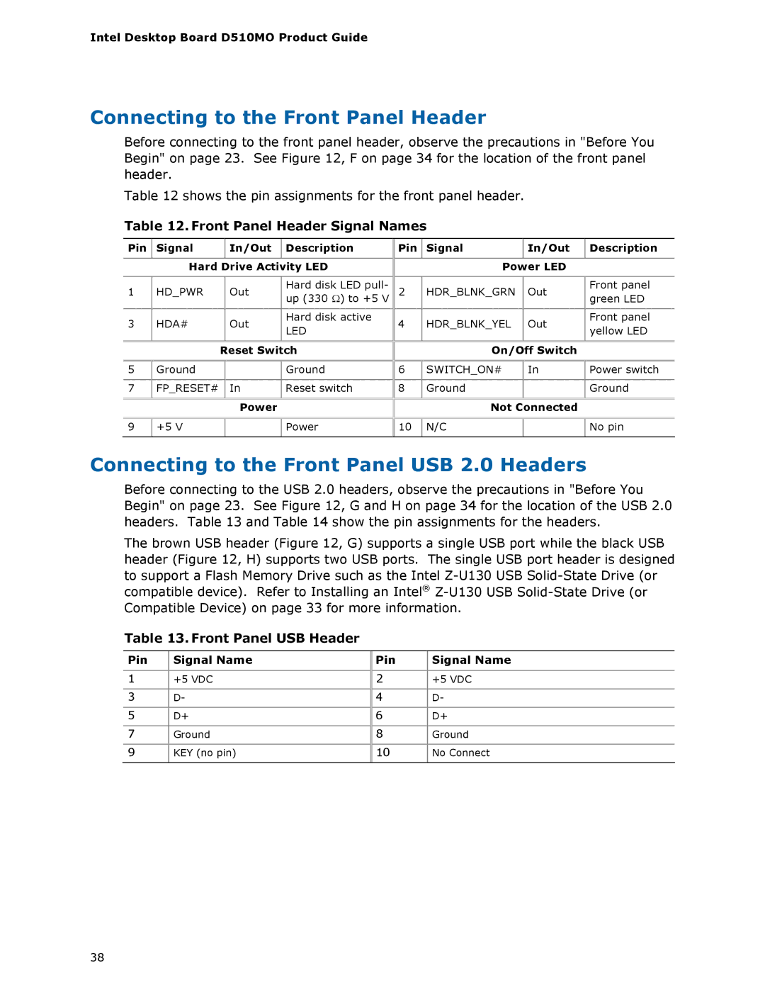
Table 12 shows the pin assignments for the front panel header.
Table 12. Front Panel Header Signal Names
Pin | Signal |
| In/Out | Description |
|
|
|
| |
| Hard Drive Activity LED | |||
|
|
|
|
|
1 | HD_PWR |
| Out | Hard disk LED pull- |
| up (330 Ω) to +5 V | |||
|
|
|
| |
|
|
|
|
|
3 | HDA# |
| Out | Hard disk active |
| LED | |||
|
|
|
| |
|
|
|
|
|
|
| Reset Switch | ||
|
|
|
|
|
Pin |
| Signal |
|
| In/Out |
| Description |
|
|
|
|
|
|
|
|
|
|
| Power LED |
|
| ||
2 |
| HDR_BLNK_GRN |
| Out |
| Front panel | |
|
|
| |||||
|
|
| green LED | ||||
|
|
|
|
|
|
| |
4 |
| HDR_BLNK_YEL |
| Out |
| Front panel | |
|
|
| yellow LED | ||||
|
|
|
|
|
|
| |
|
|
|
|
|
|
|
|
|
|
| On/Off Switch |
|
| ||
5 | Ground |
| Ground |
7 | FP_RESET# | In | Reset switch |
|
| Power |
|
|
|
| |
|
|
| |
9 | +5 V |
| Power |
|
|
|
|
6 | SWITCH_ON# | In | Power switch |
|
|
|
|
8 | Ground |
| Ground |
|
|
|
|
| Not Connected |
| |
|
|
|
|
10 | N/C |
| No pin |
|
|
|
|
Connecting to the Front Panel USB 2.0 Headers
Before connecting to the USB 2.0 headers, observe the precautions in "Before You Begin" on page 23. See Figure 12, G and H on page 34 for the location of the USB 2.0 headers. Table 13 and Table 14 show the pin assignments for the headers.
The brown USB header (Figure 12, G) supports a single USB port while the black USB header (Figure 12, H) supports two USB ports. The single USB port header is designed to support a Flash Memory Drive such as the Intel
Table 13. Front Panel USB Header
Pin Signal Name
1+5 VDC
3D-
5D+
7Ground
9KEY (no pin)
Pin | Signal Name |
2+5 VDC
4D-
6D+
8Ground
10No Connect
38