Installing and Replacing Desktop Board Components
Connecting Internal Headers
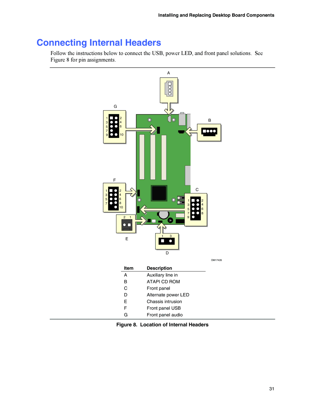
Follow the instructions below to connect the USB, power LED, and front panel solutions. See Figure 8 for pin assignments.
1
3
5
7
9
1
3
5
7
|
|
| A |
|
G |
|
|
|
|
2 |
|
|
| B |
4 |
|
|
| |
|
|
|
| |
6 |
|
|
|
|
10 |
|
|
|
|
F |
|
|
|
|
2 |
|
|
| C |
4 |
|
|
|
|
6 |
|
| 1 | 2 |
8 |
|
| ||
|
| 3 | 4 | |
10 |
|
| ||
|
| 5 | 6 | |
|
|
| ||
|
|
| 7 | 8 |
2 | 1 |
| 9 |
|
E |
| 1 | 3 |
|
|
|
|
| |
|
|
| D |
|
|
|
|
| OM17426 |
Item | Description |
| ||
A |
| Auxiliary line in |
| |
B |
| ATAPI CD ROM |
| |
C |
| Front panel |
| |
D |
| Alternate power LED |
| |
E |
| Chassis intrusion |
| |
F |
| Front panel USB |
| |
G |
| Front panel audio |
| |
Figure 8. Location of Internal Headers
31
