Installing and Replacing Desktop Board Components
Connecting Internal Headers
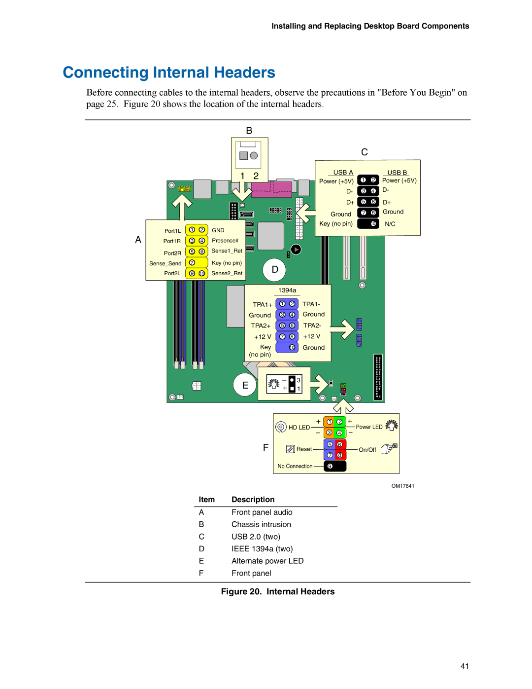
Before connecting cables to the internal headers, observe the precautions in "Before You Begin" on page 25. Figure 20 shows the location of the internal headers.
| B |
|
|
|
| |
|
|
| C |
|
| |
1 | 2 | USB A |
|
| USB B | |
Power (+5V) | 1 | 2 | Power (+5V) | |||
|
| |||||
|
| D- | 3 | 4 | D- | |
|
| D+ | 5 | 6 | D+ | |
|
| Ground | 7 | 8 | Ground | |
|
| Key (no pin) |
| 10 | N/C |
A | Port1L | 1 | 2 | GND |
|
Port1R | 3 | 4 | Presence# |
| |
| Port2R | 5 | 6 | Sense1_Ret |
|
|
|
|
|
| |
| Sense_Send | 7 |
| Key (no pin) | D |
| Port2L | 9 | 10 | Sense2_Ret | |
|
|
1394a
TPA1+ 1 2 TPA1-
Ground 3 4 Ground
TPA2+ 5 6 TPA2-
+12 V 7 8 +12 V
Key 10 Ground (no pin)![]()
![]()
E | 3 |
1 |
F
| 1 | 2 |
HD LED | 3 | Power LED |
| 4 | |
Reset | 5 | 6 |
| On/Off | |
| 7 | 8 |
No Connection | 9 |
|
OM17641
Item Description
AFront panel audio
BChassis intrusion
CUSB 2.0 (two)
DIEEE 1394a (two)
EAlternate power LED
FFront panel
Figure 20. Internal Headers
41