English
8)F_PANEL (Front Panel Jumper)
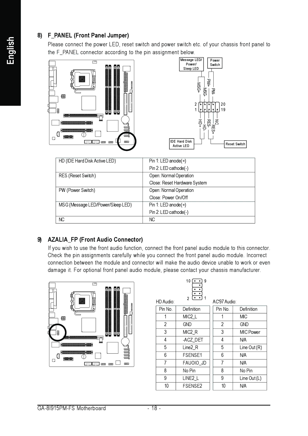
Please connect the power LED, reset switch and power switch etc. of your chassis front panel to the F_PANEL connector according to the pin assignment below.
Message LED/ |
| Power | |||||
Power/ |
| Switch | |||||
Sleep LED |
|
|
|
|
| ||
|
|
|
|
|
|
|
|
IDE Hard Disk
Active LED
MSG+ | PW+ |
|
MSG- | PW- | |
2 |
| 2 0 |
1 |
| 1 9 |
RES+ RES- HD- HD+ | ||
|
| NC |
![]()
![]() Reset Switch
Reset Switch
HD (IDE Hard Disk Active LED) | Pin 1: LED anode(+) |
| Pin 2: LED |
RES (Reset Switch) | Open: Normal Operation |
| Close: Reset Hardware System |
|
|
PW (Power Switch) | Open: Normal Operation |
| Close: Power On/Off |
MSG (Message LED/Power/Sleep LED) | Pin 1: LED anode(+) |
| Pin 2: LED |
NC | NC |
9)AZALIA_FP (Front Audio Connector)
If you wish to use the front audio function, connect the front panel audio module to this connector. Check the pin assignments carefully while you connect the front panel audio module. Incorrect connection between the module and connector will make the audio device unable to work or even damage it. For optional front panel audio module, please contact your chassis manufacturer.
| 1 0 | 9 |
HD Audio: | 2 | 1 |
|
| |
|
|
|
Pin No. | Definition |
|
1 | MIC2_L |
|
2 | GND |
|
3 | MIC2_R |
|
4 |
| |
5 | Line2_R |
|
6 | FSENSE1 |
|
7 | FAUOIO_JD | |
8 | No Pin |
|
9 | LINE2_L |
|
10 | FSENSE2 |
|
AC'97 Audio:
Pin No. | Definition | |
1 | MIC |
|
2 | GND |
|
3 | MIC Power |
|
4 | N/A |
|
5 | Line Out (R) |
|
6 | N/A |
|
7 | N/A |
|
8 | No Pin |
|
9 | Line Out (L) |
|
10 | N/A |
|
- 18 - |