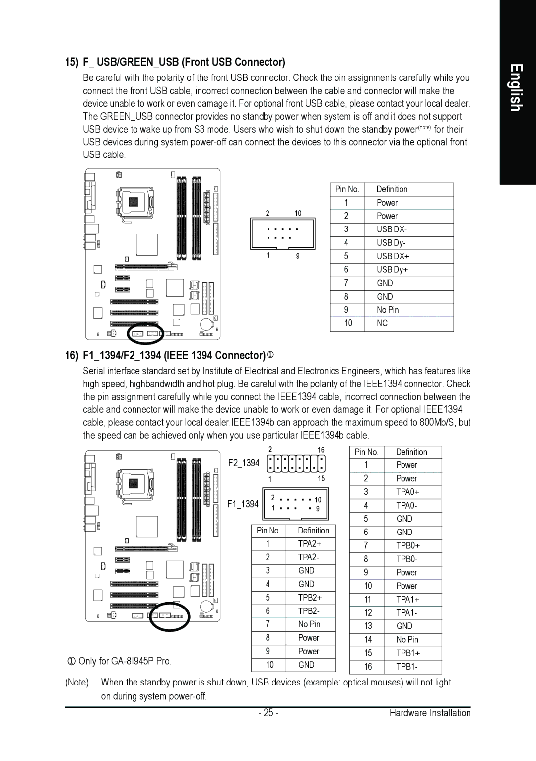
15)F_ USB/GREEN_USB (Front USB Connector)
Be careful with the polarity of the front USB connector. Check the pin assignments carefully while you connect the front USB cable, incorrect connection between the cable and connector will make the device unable to work or even damage it. For optional front USB cable, please contact your local dealer. The GREEN_USB connector provides no standby power when system is off and it does not support USB device to wake up from S3 mode. Users who wish to shut down the standby power(note) for their USB devices during system
|
|
|
| Pin No. | Definition |
2 |
| 10 |
| 1 | Power |
|
| 2 | Power | ||
|
|
|
| 3 | USB DX- |
|
|
|
| 4 | USB Dy- |
|
|
|
|
|
|
1 |
| 9 |
| 5 | USB DX+ |
|
|
|
| 6 | USB Dy+ |
|
|
|
| 7 | GND |
|
|
|
| 8 | GND |
|
|
|
| 9 | No Pin |
|
|
|
| 10 | NC |
|
|
|
|
|
|
16)F1_1394/F2_1394 (IEEE 1394 Connector)
Serial interface standard set by Institute of Electrical and Electronics Engineers, which has features like high speed, highbandwidth and hot plug. Be careful with the polarity of the IEEE1394 connector. Check the pin assignment carefully while you connect the IEEE1394 cable, incorrect connection between the cable and connector will make the device unable to work or even damage it. For optional IEEE1394 cable, please contact your local dealer.IEEE1394b can approach the maximum speed to 800Mb/S, but the speed can be achieved only when you use particular IEEE1394b cable.
F2_1394 | 2 | 16 | Pin No. | Definition | |
|
| 1 | Power | ||
| 1 | 15 | 2 | Power | |
F1_1394 | 2 | 10 | 3 | TPA0+ | |
4 | TPA0- | ||||
1 | 9 | ||||
Pin No. | Definition | 5 | GND | ||
6 | GND | ||||
| 1 | TPA2+ | 7 | TPB0+ | |
| 2 | TPA2- | 8 | TPB0- | |
| 3 | GND | 9 | Power | |
| 4 | GND | 10 | Power | |
| 5 | TPB2+ | 11 | TPA1+ | |
| 6 | TPB2- | 12 | TPA1- | |
| 7 | No Pin | 13 | GND | |
| 8 | Power | 14 | No Pin | |
Only for | 9 | Power | 15 | TPB1+ | |
10 | GND | 16 | TPB1- | ||
| |||||
(Note) When the standby power is shut down, USB devices (example: optical mouses) will not light
on during system |
|
- 25 - | Hardware Installation |
English
