| I/O Port Pin Assignment |
Appendix A <I/O Port Pin Assignment>
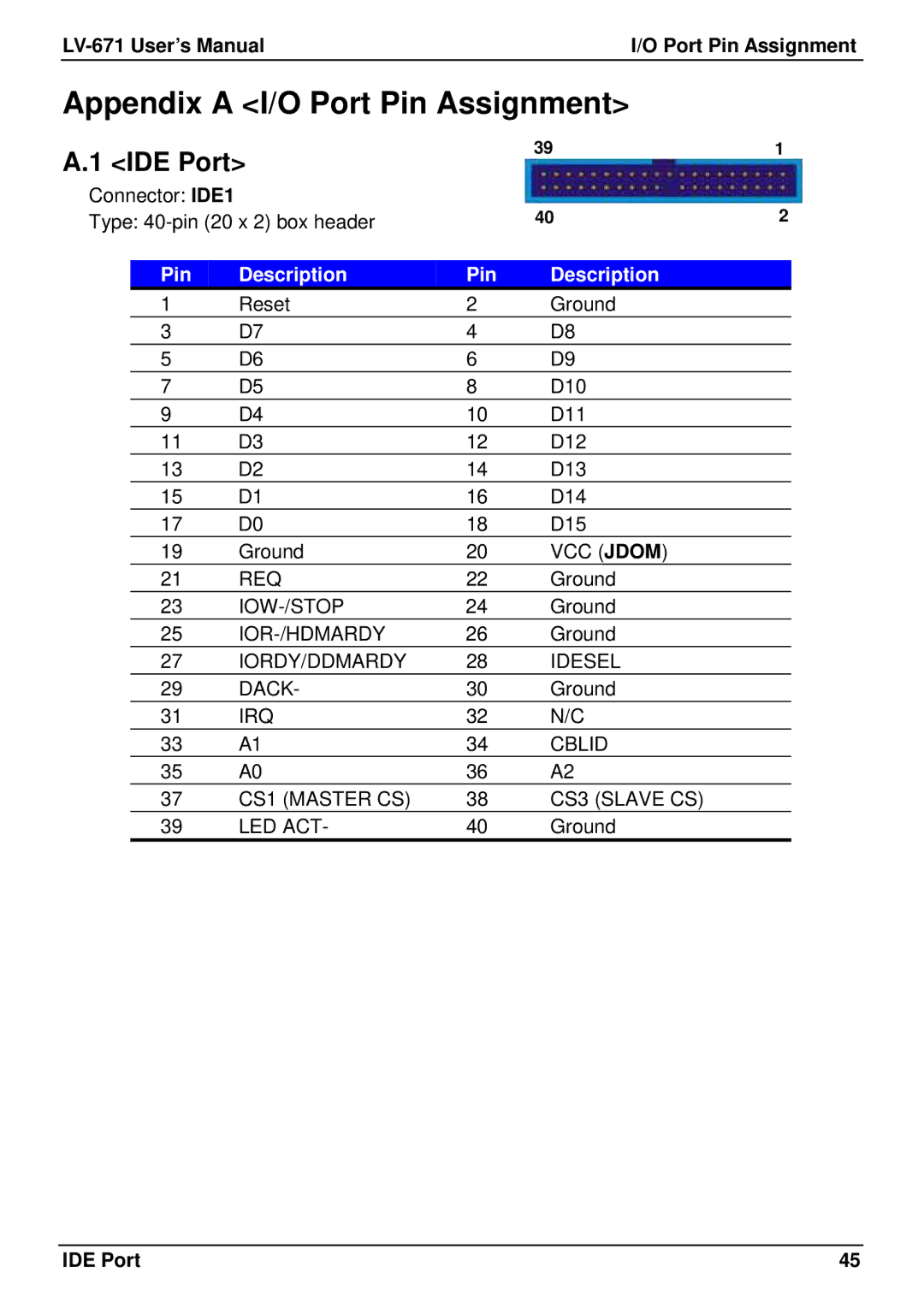
A.1 <IDE Port> |
| 39 | ||
|
| |||
Connector: IDE1 |
|
| 40 | |
Type: |
| |||
|
|
|
| Description |
| Pin | Description | Pin | |
| 1 | Reset | 2 | Ground |
| 3 | D7 | 4 | D8 |
| 5 | D6 | 6 | D9 |
| 7 | D5 | 8 | D10 |
| 9 | D4 | 10 | D11 |
| 11 | D3 | 12 | D12 |
| 13 | D2 | 14 | D13 |
| 15 | D1 | 16 | D14 |
| 17 | D0 | 18 | D15 |
| 19 | Ground | 20 | VCC (JDOM) |
| 21 | REQ | 22 | Ground |
| 23 | 24 | Ground | |
| 25 | 26 | Ground | |
| 27 | IORDY/DDMARDY | 28 | IDESEL |
| 29 | DACK- | 30 | Ground |
| 31 | IRQ | 32 | N/C |
| 33 | A1 | 34 | CBLID |
| 35 | A0 | 36 | A2 |
| 37 | CS1 (MASTER CS) | 38 | CS3 (SLAVE CS) |
39 | LED ACT- | 40 | Ground | |
1
2
IDE Port | 45 |
