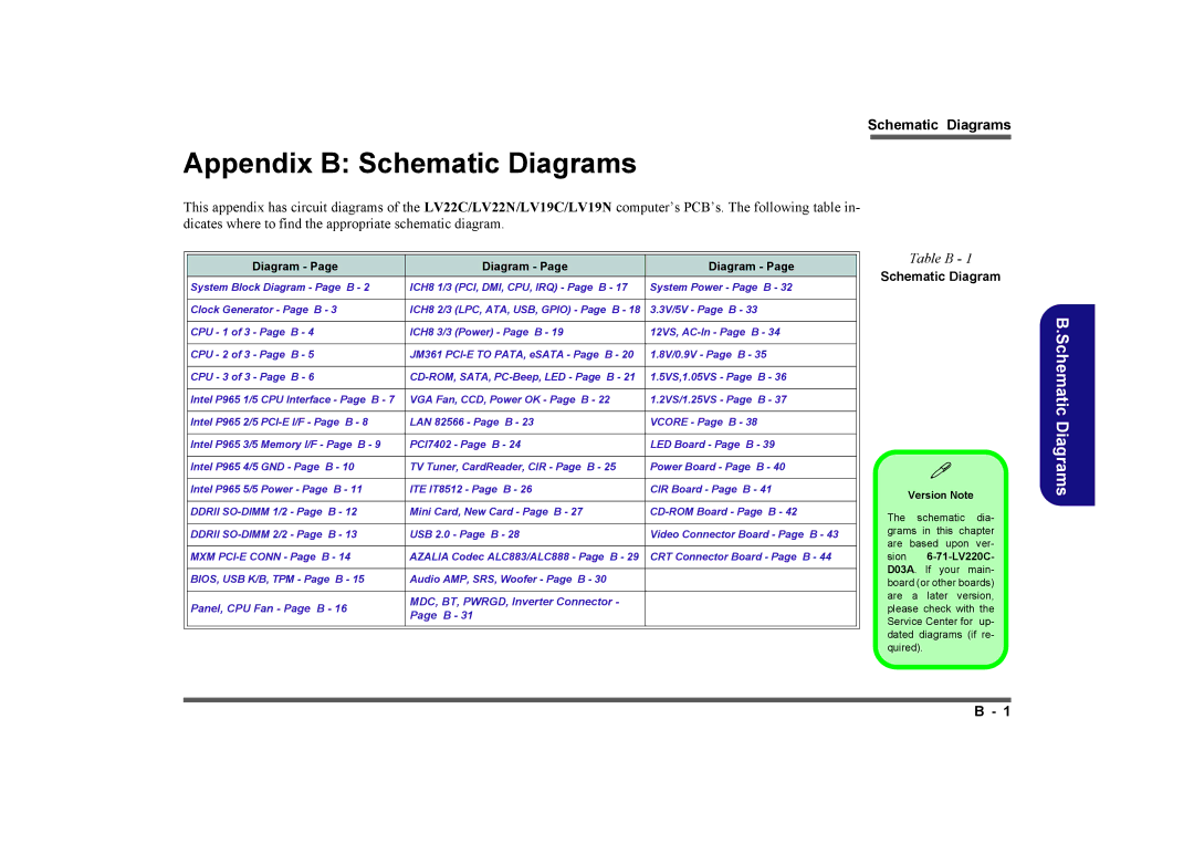
LV19N Series, LV19C Series, LV22C Series, LV22N Series specifications
Intel has consistently pushed the boundaries of technology, and its LV22N, LV22C, LV19C, and LV19N series processors are prime examples of its commitment to innovation and performance. These processors are built to cater to a wide range of applications, from embedded systems to energy-efficient computing, making them versatile solutions for various industries.The Intel LV22N Series stands out with its advanced fabrication technology, providing improved performance per watt compared to previous generations. With features such as enhanced multi-core processing capabilities, these processors are designed to handle demanding workloads effectively. The LV22N series supports Intel's latest architecture, allowing for increased cache sizes and memory bandwidth. This enhances data processing capabilities, making it ideal for edge computing and IoT applications. Precision timing and security features such as Intel Hardware Shield further bolster its reliability.
On the other hand, the LV22C Series is tailored for high-performance computing tasks. It supports Intel's deep learning and Artificial Intelligence (AI) capabilities, enabling developers to create smarter applications. The LV22C processors offer integrated graphics that deliver superior multimedia performance, ensuring smooth video playback and graphics rendering. These processors also come equipped with Intel’s Turbo Boost Technology, which optimizes performance by dynamically increasing clock speeds when necessary.
The LV19C Series targets energy-efficient solutions without sacrificing performance. This series is particularly beneficial for mobile applications, allowing devices to run longer on a single charge. With features like Dynamic Tuning Technology, LV19C processors adjust power consumption based on workload, which enhances battery life and thermal performance. This focus on efficiency helps reduce the total cost of ownership for devices used in various sectors.
Lastly, the LV19N Series combines low power consumption with high-performance capabilities. It's engineered for use in compact, thermal-constrained environments, making it an excellent choice for embedded systems. The LV19N processors incorporate advanced security features to safeguard data while offering reliable connectivity options for Internet of Things (IoT) deployments.
In summary, the Intel LV22N, LV22C, LV19C, and LV19N series processors represent a significant leap in technology, characterized by their performance, efficiency, and specialized features. With their diverse applications, these series provide solutions that accommodate the evolving demands of computing, making them indispensable in the modern technological landscape.

