Evaluation Board for Octal E1 Applications — LXD381
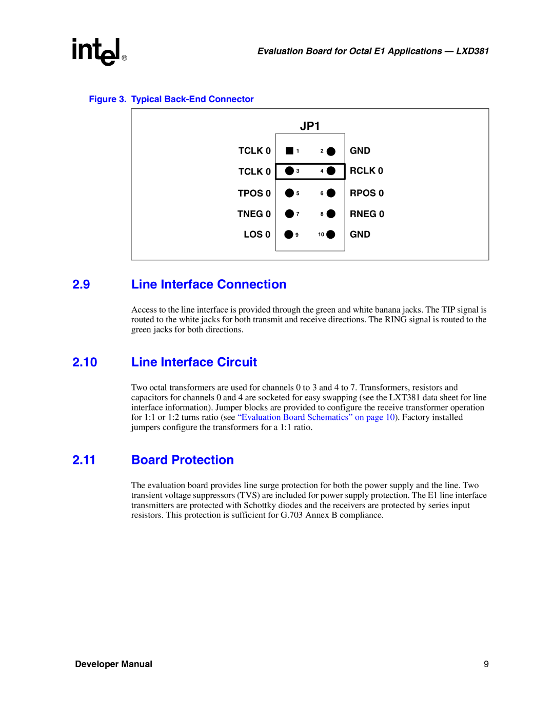
Figure 3. Typical Back-End Connector
TCLK 0
TCLK 0
TPOS 0
TNEG 0
LOS 0
| JP1 |
1 | 2 |
3 | 4 |
5 | 6 |
7 | 8 |
9 | 10 |
GND
RCLK 0
RPOS 0
RNEG 0
GND
2.9Line Interface Connection
Access to the line interface is provided through the green and white banana jacks. The TIP signal is routed to the white jacks for both transmit and receive directions. The RING signal is routed to the green jacks for both directions.
2.10Line Interface Circuit
Two octal transformers are used for channels 0 to 3 and 4 to 7. Transformers, resistors and capacitors for channels 0 and 4 are socketed for easy swapping (see the LXT381 data sheet for line interface information). Jumper blocks are provided to configure the receive transformer operation for 1:1 or 1:2 turns ratio (see “Evaluation Board Schematics” on page 10). Factory installed jumpers configure the transformers for a 1:1 ratio.
2.11Board Protection
The evaluation board provides line surge protection for both the power supply and the line. Two transient voltage suppressors (TVS) are included for power supply protection. The E1 line interface transmitters are protected with Schottky diodes and the receivers are protected by series input resistors. This protection is sufficient for G.703 Annex B compliance.
Developer Manual | 9 |