AXIS Q1635 Fixed Network Camera
Technical Specifications
Function/group | Item | Specifications |
|
|
|
| Optional | AXIS T8414 Installation Display |
| accessories | AXIS Power over Ethernet Midspan |
|
| AXIS Camera Station and video management software from Axis’ Application |
|
| Development Partners |
|
|
|
| Languages | German, French, Spanish, Italian, Russian, Simplified Chinese, Japanese, Korean, |
|
| Portuguese |
|
|
|
| Warranty | Axis |
|
|
|
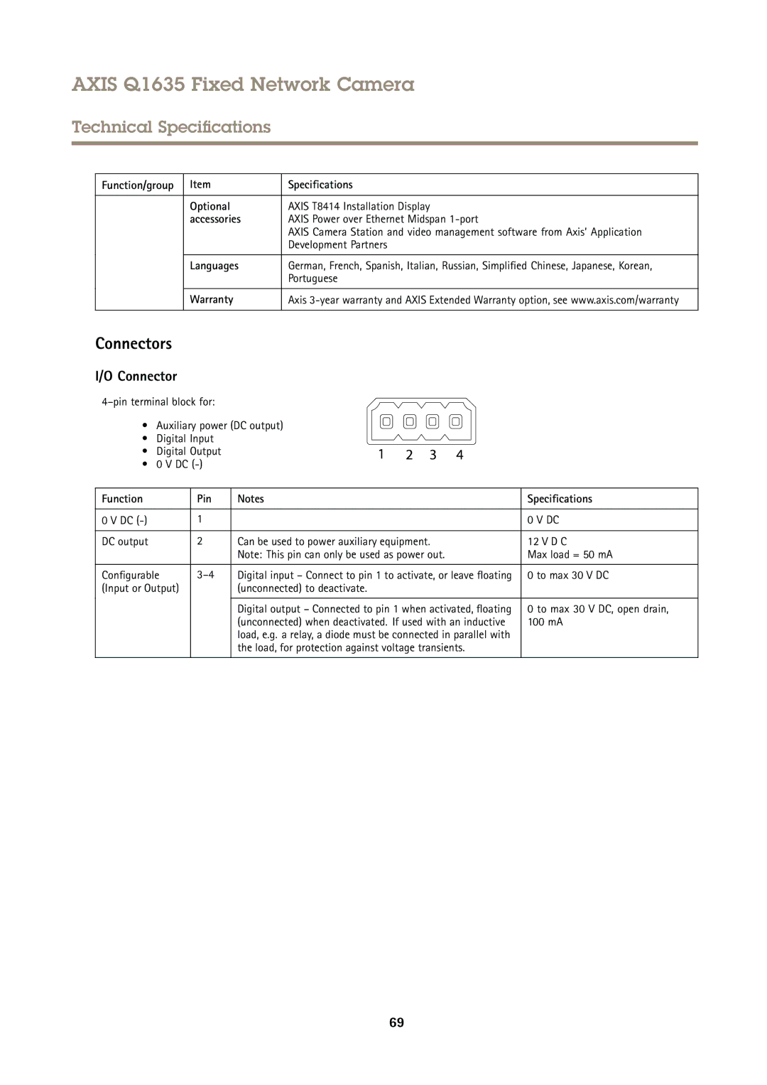
Connectors
I/O Connector
• Auxiliary power (DC output)
• Digital Input
• Digital Output
• 0 V DC
Function | Pin | Notes | Specifications |
|
|
|
|
0 V DC | 1 |
| 0 V DC |
|
|
|
|
DC output | 2 | Can be used to power auxiliary equipment. | 12 V D C |
|
| Note: This pin can only be used as power out. | Max load = 50 mA |
|
|
|
|
Configurable | Digital input – Connect to pin 1 to activate, or leave floating | 0 to max 30 V DC | |
(Input or Output) |
| (unconnected) to deactivate. |
|
|
|
|
|
|
| Digital output – Connected to pin 1 when activated, floating | 0 to max 30 V DC, open drain, |
|
| (unconnected) when deactivated. If used with an inductive | 100 mA |
|
| load, e.g. a relay, a diode must be connected in parallel with |
|
|
| the load, for protection against voltage transients. |
|
|
|
|
|
69