INSTALLATIONS
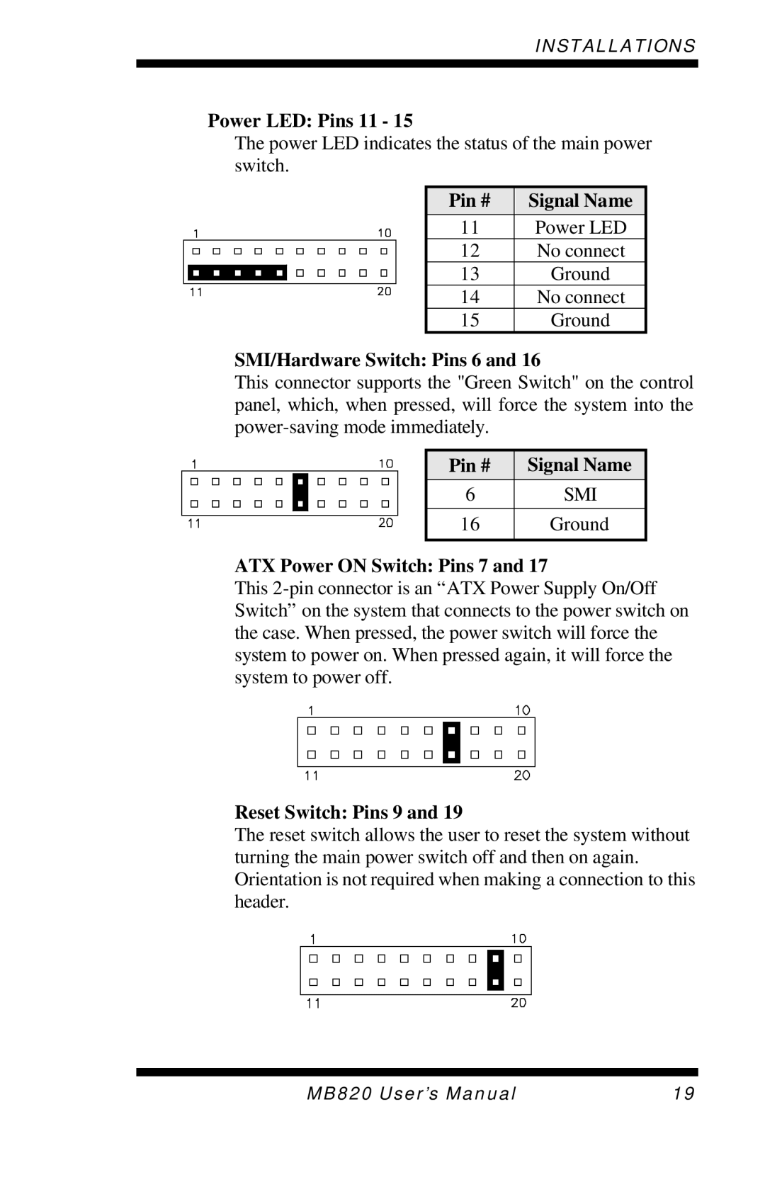
Power LED: Pins 11 - 15
The power LED indicates the status of the main power switch.
Pin # | Signal Name |
11 | Power LED |
12 | No connect |
13 | Ground |
14 | No connect |
15 | Ground |
SMI/Hardware Switch: Pins 6 and 16
This connector supports the "Green Switch" on the control panel, which, when pressed, will force the system into the
Pin # | Signal Name |
6 | SMI |
|
|
16 | Ground |
|
|
ATX Power ON Switch: Pins 7 and 17
This
Reset Switch: Pins 9 and 19
The reset switch allows the user to reset the system without turning the main power switch off and then on again. Orientation is not required when making a connection to this header.
MB820 User’s Manual | 19 |