INSTALLATIONS
ATX Power ON Switch: Pins 7 and 17
This
Reset Switch: Pins 9 and 19
The reset switch allows the user to reset the system without turning the main power switch off and then on again. Orientation is not required when making a connection to this header.
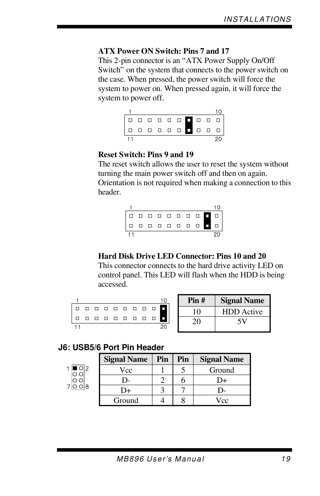
Hard Disk Drive LED Connector: Pins 10 and 20 This connector connects to the hard drive activity LED on control panel. This LED will flash when the HDD is being accessed.
|
| Pin # | Signal Name |
|
| 10 | HDD Active |
|
| 20 | 5V |
J6: USB5/6 Port Pin Header |
|
| |
Signal Name | Pin | Pin Signal Name | |
Vcc | 1 | 5 | Ground |
D- | 2 | 6 | D+ |
D+ | 3 | 7 | D- |
Ground | 4 | 8 | Vcc |
MB896 User’s Manual | 19 |