BT1
CN21
DI MM1
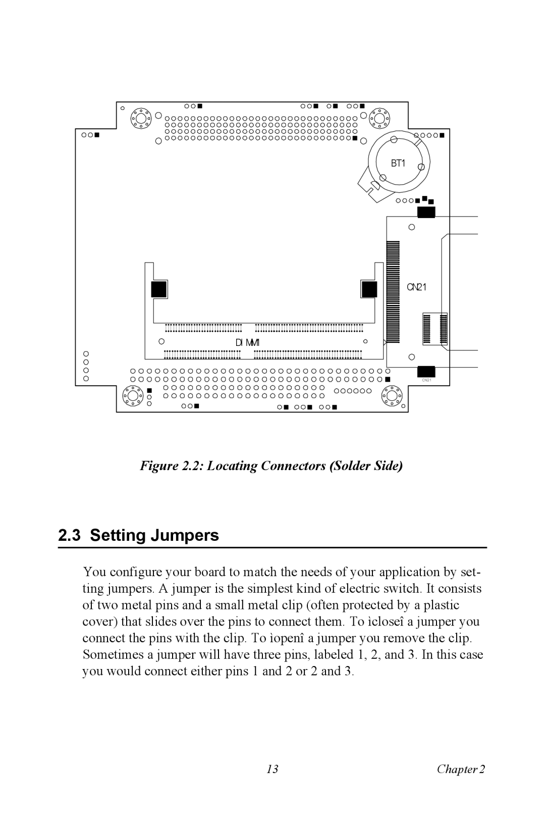
Figure 2.2: Locating Connectors (Solder Side)
2.3 Setting Jumpers
You configure your board to match the needs of your application by set- ting jumpers. A jumper is the simplest kind of electric switch. It consists of two metal pins and a small metal clip (often protected by a plastic cover) that slides over the pins to connect them. To ìcloseî a jumper you connect the pins with the clip. To ìopenî a jumper you remove the clip. Sometimes a jumper will have three pins, labeled 1, 2, and 3. In this case you would connect either pins 1 and 2 or 2 and 3.
13 | Chapter2 |