MDRIVE17 SPEED CONTROL SPECIFICATIONS
GENERAL SPECIFICATIONS
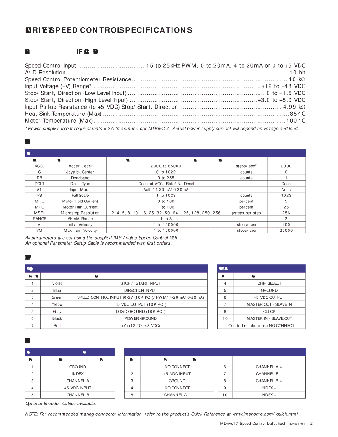
Speed Control Input | 15 to 25kHz PWM, 0 to 20mA, 4 to 20mA or 0 to +5 | VDC | |
A/D Resolution | 10 bit | ||
Speed Control Potentiometer Resistance | 10 kΩ | ||
Input Voltage (+V) Range* | +12 to +48 | VDC | |
Stop/Start, Direction (Low Level Input) | 0 to +1.5 | VDC | |
Stop/Start, Direction (High Level Input) | +3.0 to +5.0 | VDC | |
Input | ...................................................... 4.99 kΩ | ||
Heat Sink Temperature (Max) | 85° C | ||
Motor Temperature (Max) | 100° C | ||
*Power supply current requirements = 2A (maximum) per MDrive17. Actual power supply current will depend on voltage and load.
PARAMETERS
SETUP PARAMETERS
NAME | FUNCTION | RANGE | UNITS | DEFAULT |
ACCL | Accel/Decel | 2000 to 65000 | steps/sec2 | 2000 |
C | Joystick Center | 0 to 1022 | counts | 0 |
DB | Deadband | 0 to 255 | counts | 1 |
DCLT | Decel Type | Decel at ACCL Rate/No Decel | Decel | |
A1 | Input Mode | Volts | ||
FS | Full Scale | 1 to 1023 | counts | 1023 |
MHC | Motor Hold Current | 0 to 100 | percent | 5 |
MRC | Motor Run Current | 1 to 100 | percent | 25 |
MSEL | Microstep Resolution | 2, 4, 5, 8, 10, 16, 25, 32, 50, 64, 125, 128, 250, 256 | µsteps per step | 256 |
RANGE | VI/VM Range | 1 to 8 | 3 | |
VI | Initial Velocity | 1 to 100000 | steps/sec | 400 |
VM | Maximum Velocity | 1 to 100000 | steps/sec | 20000 |
All parameters are set using the supplied IMS Analog Speed Control GUI. An optional Parameter Setup Cable is recommended with first orders.
PIN/WIRE ASSIGNMENTS
CONNECTOR P1 – Pluggable Terminal Strip or Flying Leads
PIN | FLYING LEADS | FUNCTION |
|
|
|
1 | Violet | STOP / START INPUT |
|
|
|
2 | Blue | DIRECTION INPUT |
|
|
|
3 | Green | SPEED CONTROL INPUT |
|
|
|
4 | Yellow | +5 VDC OUTPUT (10K POT) |
|
|
|
5 | Gray | LOGIC GROUND (10K POT) |
|
|
|
6 | Black | POWER GROUND |
|
|
|
7 | Red | +V (+12 TO +48 VDC) |
|
|
|
CONNECTOR P2 (SPI) – 10 Pin
PINFUNCTION
4CHIP SELECT
5GROUND
6+5 VDC OUTPUT
7MASTER OUT - SLAVE IN
8CLOCK
10MASTER IN - SLAVE OUT Omitted numbers are NO CONNECT
ENCODER PIN ASSIGNMENTS
ENCODER –
PIN | FUNCTION |
1 | GROUND |
|
|
2 | INDEX |
3CHANNEL A
4+5 VDC INPUT
5CHANNEL B
Optional Encoder Cables available.
ENCODER – Differential
PIN | FUNCTION |
| PIN | FUNCTION |
|
|
|
|
|
1 | NO CONNECT |
| 6 | CHANNEL A + |
|
|
|
|
|
2 | +5 VDC INPUT |
| 7 | CHANNEL B – |
|
|
|
|
|
3 | GROUND |
| 8 | CHANNEL B + |
|
|
|
|
|
4 | NO CONNECT |
| 9 | INDEX – |
|
|
|
|
|
5 | CHANNEL A – |
| 10 | INDEX + |
|
|
|
|
|
NOTE: For recommended mating connector information, refer to the product's Quick Reference at www.imshome.com/quick.html
MDrive17 Speed Control Datasheet REV121704 2