MDRIVE17 SPEED CONTROL – MECHANICAL SPECIFICATIONS
Dimensions in Inches (mm)
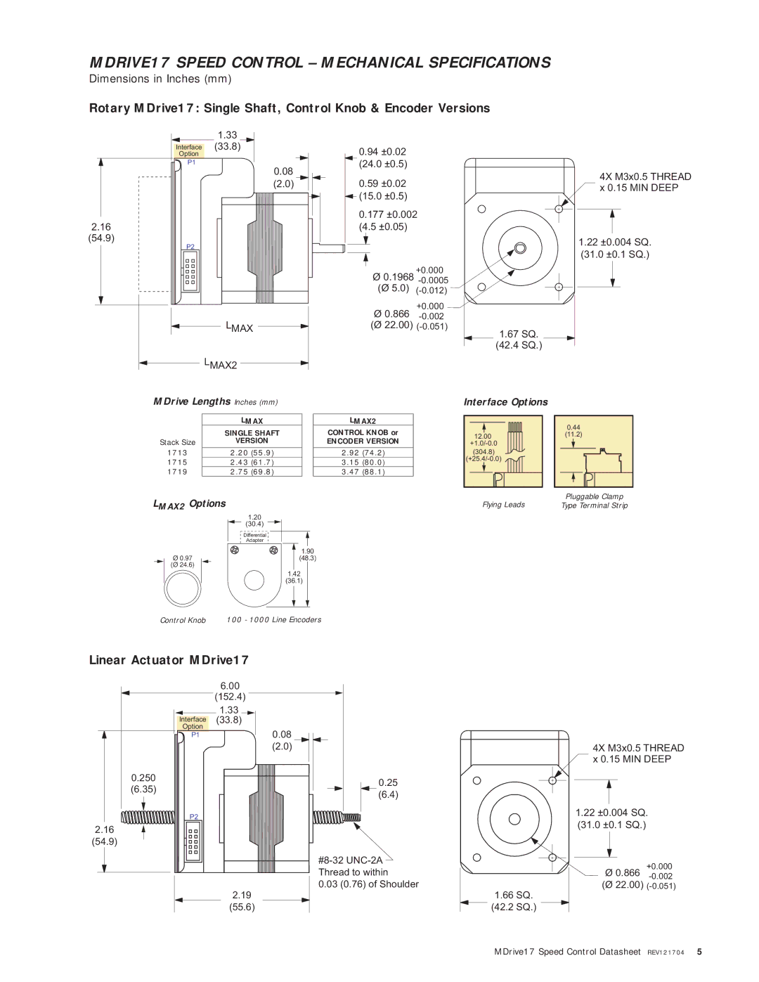
Rotary MDrive17: Single Shaft, Control Knob & Encoder Versions
1.33
Interface (33.8)
Option
P1
0.08
(2.0)
2.16
(54.9)
P2
LMAX
LMAX2
MDrive Lengths Inches (mm)
0.94±0.02 (24.0 ±0.5)
0.59±0.02 ![]() (15.0 ±0.5)
(15.0 ±0.5)
0.177 ±0.002
(4.5 ±0.05)
Ø 0.1968
+0.000
Ø0.866
(Ø 22.00)
4X M3x0.5 THREAD ![]() x 0.15 MIN DEEP
x 0.15 MIN DEEP
1.22 ±0.004 SQ.
(31.0 ±0.1 SQ.)
1.67SQ.
(42.4 SQ.)
Interface Options
| LMAX |
| SINGLE SHAFT |
Stack Size | VERSION |
1713 | 2.20 (55.9) |
1715 | 2.43 (61.7) |
1719 | 2.75 (69.8) |
LMAX2
CONTROL KNOB or
ENCODER VERSION
2.92(74.2)
3.15(80.0)
3.47 (88.1)
12.00
(304.8)
0.44 |
(11.2) |
Pluggable Clamp
LMAX2 Options
| 1.20 |
| (30.4) |
| Differential |
| Adapter |
Ø 0.97 | 1.90 |
(48.3) | |
(Ø 24.6) |
|
| 1.42 |
| (36.1) |
| . |
Control Knob | 100 - 1000 Line Encoders |
Flying Leads
Type Terminal Strip
Linear Actuator MDrive17
6.00
(152.4)
1.33 ![]()
Interface (33.8)
Option
P1 | 0.08 |
| (2.0) |
0.250
(6.35)
![]()
![]()
![]()
![]() P2
P2![]()
![]()
![]()
![]()
![]()
![]()
![]()
![]()
2.16
(54.9)
2.19
(55.6)
0.25
(6.4)
0.03 (0.76) of Shoulder
1.66SQ.
(42.2 SQ.)
4X M3x0.5 THREAD x 0.15 MIN DEEP
1.22±0.004 SQ. (31.0 ±0.1 SQ.)
+0.000 Ø 0.866
(Ø 22.00)
MDrive17 Speed Control Datasheet REV121704 5