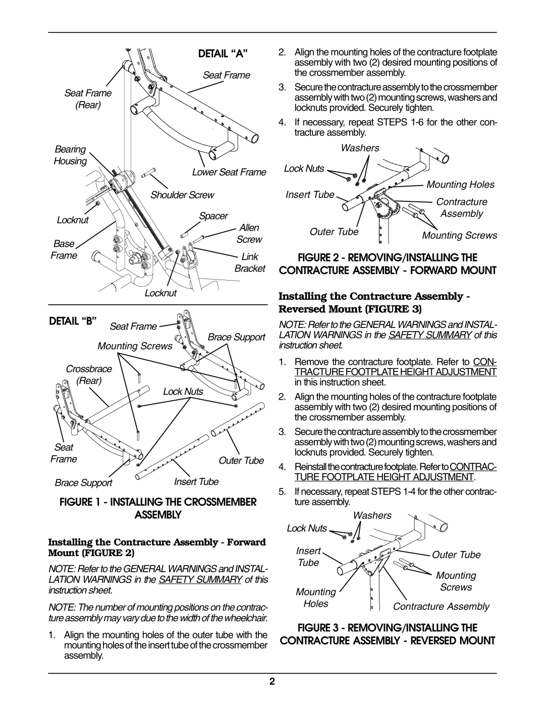
Seat Frame
(Rear)
Bearing
Housing
Locknut
Base
Frame
DETAIL “A”
Seat Frame
Lower Seat Frame
Shoulder Screw
Spacer
Allen
Screw
Link
Bracket
Locknut
2.Align the mounting holes of the contracture footplate assembly with two (2) desired mounting positions of the crossmember assembly.
3.Securethecontractureassemblytothecrossmember assembly with two (2) mounting screws, washers and locknuts provided. Securely tighten.
4.If necessary, repeat STEPS
| Washers |
| |
Lock Nuts |
| Mounting Holes | |
| |||
Insert Tube | |||
Contracture | |||
|
| ||
|
| Assembly | |
Outer Tube | Mounting Screws | ||
|
| ||
FIGURE 2 - REMOVING/INSTALLING THE
CONTRACTURE ASSEMBLY - FORWARD MOUNT
Installing the Contracture Assembly - Reversed Mount (FIGURE 3)
DETAIL “B” Seat Frame
Brace Support
Mounting Screws
Crossbrace
(Rear)
Lock Nuts
Seat |
|
Frame | Outer Tube |
Brace Support | Insert Tube |
FIGURE 1 - INSTALLING THE CROSSMEMBER
ASSEMBLY
Installing the Contracture Assembly - Forward Mount (FIGURE 2)
NOTE: Refer to the GENERAL WARNINGS and INSTAL- LATION WARNINGS in the SAFETY SUMMARY of this instruction sheet.
NOTE: The number of mounting positions on the contrac- ture assembly may vary due to the width of the wheelchair.
1.Align the mounting holes of the outer tube with the mounting holes of the insert tube of the crossmember assembly.
NOTE: Refer to the GENERAL WARNINGS and INSTAL- LATION WARNINGS in the SAFETY SUMMARY of this instruction sheet.
1.Remove the contracture footplate. Refer to CON-
TRACTURE FOOTPLATE HEIGHT ADJUSTMENT in this instruction sheet.
2.Align the mounting holes of the contracture footplate assembly with two (2) desired mounting positions of the crossmember assembly.
3.Securethecontractureassemblytothecrossmember assembly with two (2) mounting screws, washers and locknuts provided. Securely tighten.
4.Reinstallthecontracturefootplate.RefertoCONTRAC-
TURE FOOTPLATE HEIGHT ADJUSTMENT.
5.If necessary, repeat STEPS
Washers
Lock Nuts |
| |
Insert | Outer Tube | |
Tube | ||
| ||
| Mounting | |
Mounting | Screws | |
| ||
Holes | Contracture Assembly |
FIGURE 3 - REMOVING/INSTALLING THE
CONTRACTURE ASSEMBLY - REVERSED MOUNT
2