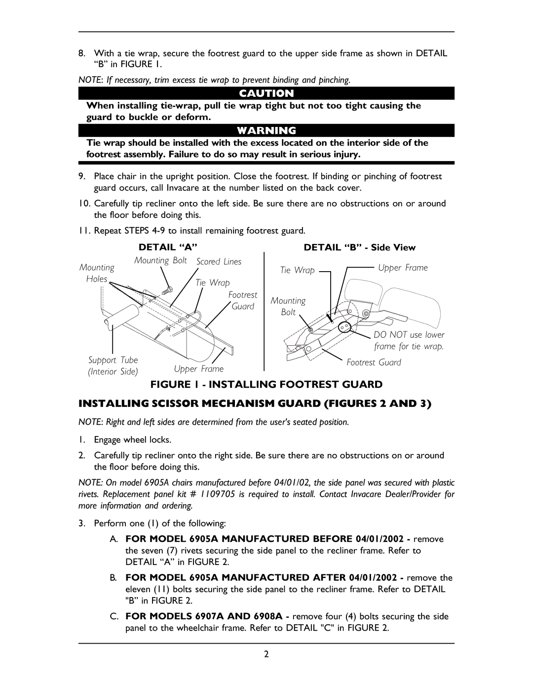
8.With a tie wrap, secure the footrest guard to the upper side frame as shown in DETAIL “B” in FIGURE 1.
NOTE: If necessary, trim excess tie wrap to prevent binding and pinching.
CAUTION
When installing
WARNING
Tie wrap should be installed with the excess located on the interior side of the footrest assembly. Failure to do so may result in serious injury.
9.Place chair in the upright position. Close the footrest. If binding or pinching of footrest guard occurs, call Invacare at the number listed on the back cover.
10.Carefully tip recliner onto the left side. Be sure there are no obstructions on or around the floor before doing this.
11.Repeat STEPS
DETAIL “A”
Mounting | Mounting Bolt Scored Lines | |
|
| |
Holes |
| Tie Wrap |
|
| |
|
| Footrest |
|
| Guard |
Support Tube | Upper Frame | |
(Interior Side) | ||
DETAIL “B” - Side View
Tie Wrap |
| Upper Frame |
|
Mounting
Bolt
DO NOT use lower frame for tie wrap.
Footrest Guard
FIGURE 1 - INSTALLING FOOTREST GUARD
INSTALLING SCISSOR MECHANISM GUARD (FIGURES 2 AND 3)
NOTE: Right and left sides are determined from the user's seated position.
1.Engage wheel locks.
2.Carefully tip recliner onto the right side. Be sure there are no obstructions on or around the floor before doing this.
NOTE: On model 6905A chairs manufactured before 04/01/02, the side panel was secured with plastic rivets. Replacement panel kit # 1109705 is required to install. Contact Invacare Dealer/Provider for more information and ordering.
3.Perform one (1) of the following:
A.FOR MODEL 6905A MANUFACTURED BEFORE 04/01/2002 - remove the seven (7) rivets securing the side panel to the recliner frame. Refer to DETAIL “A” in FIGURE 2.
B.FOR MODEL 6905A MANUFACTURED AFTER 04/01/2002 - remove the eleven (11) bolts securing the side panel to the recliner frame. Refer to DETAIL "B” in FIGURE 2.
C.FOR MODELS 6907A AND 6908A - remove four (4) bolts securing the side panel to the wheelchair frame. Refer to DETAIL "C" in FIGURE 2.
2