SEAT AND BACK | PROCEDURE 3 |
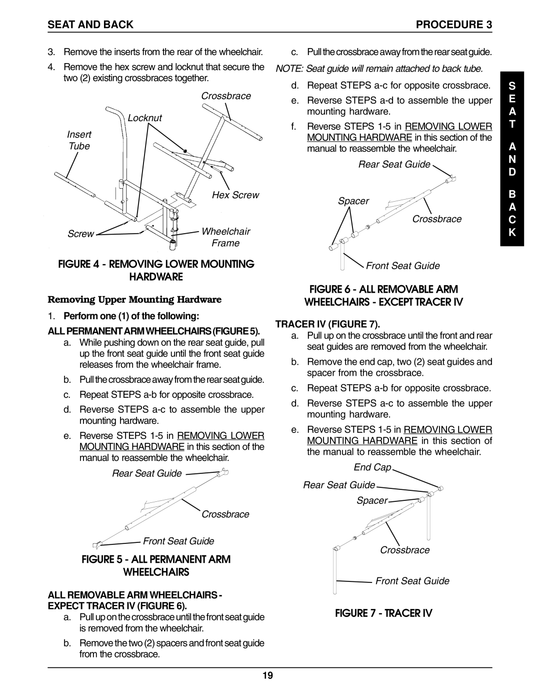
3.Remove the inserts from the rear of the wheelchair.
4.Remove the hex screw and locknut that secure the two (2) existing crossbraces together.
Crossbrace
Locknut
Insert
Tube
| Hex Screw |
Screw | Wheelchair |
| Frame |
FIGURE 4 - REMOVING LOWER MOUNTING
HARDWARE
Removing Upper Mounting Hardware
1.Perform one (1) of the following:
ALL PERMANENT ARM WHEELCHAIRS (FIGURE 5).
a.While pushing down on the rear seat guide, pull up the front seat guide until the front seat guide releases from the wheelchair frame.
b.Pull the crossbrace away from the rear seat guide.
c.Repeat STEPS
d.Reverse STEPS
e.Reverse STEPS
Rear Seat Guide
Crossbrace
 Front Seat Guide
FIGURE 5 - ALL PERMANENT ARM
WHEELCHAIRS
ALL REMOVABLE ARM WHEELCHAIRS - EXPECT TRACER IV (FIGURE 6).
a.Pull up on the crossbrace until the front seat guide is removed from the wheelchair.
c. Pull the crossbrace away from the rear seat guide.
NOTE: Seat guide will remain attached to back tube.
d.Repeat STEPS
e.Reverse STEPS
f.Reverse STEPS
Rear Seat Guide
Spacer
Crossbrace
Front Seat Guide
FIGURE 6 - ALL REMOVABLE ARM
WHEELCHAIRS - EXCEPT TRACER IV
TRACER IV (FIGURE 7).
a.Pull up on the crossbrace until the front and rear seat guides are removed from the wheelchair.
b.Remove the end cap, two (2) seat guides and spacer from the crossbrace.
c.Repeat STEPS
d.Reverse STEPS
e.Reverse STEPS
End Cap
Rear Seat Guide
Spacer ![]()
Crossbrace
![]() Front Seat Guide
Front Seat Guide
FIGURE 7 - TRACER IV
S E A T
A N D
B A C K
b.Remove the two (2) spacers and front seat guide from the crossbrace.
19
