| PROCEDURE 7 |
This Procedure Includes the Following:
Installing/Adjusting
Wheel Lock Adjustment
WARNING
After ANY adjustments, repair or service and BE- FORE use, make sure all attaching hardware is tightened securely - otherwise injury or damage may result.
INSTALLING/ADJUSTING THE ANTI-TIPPERS
WARNING
Inasmuch as the
Ensure both
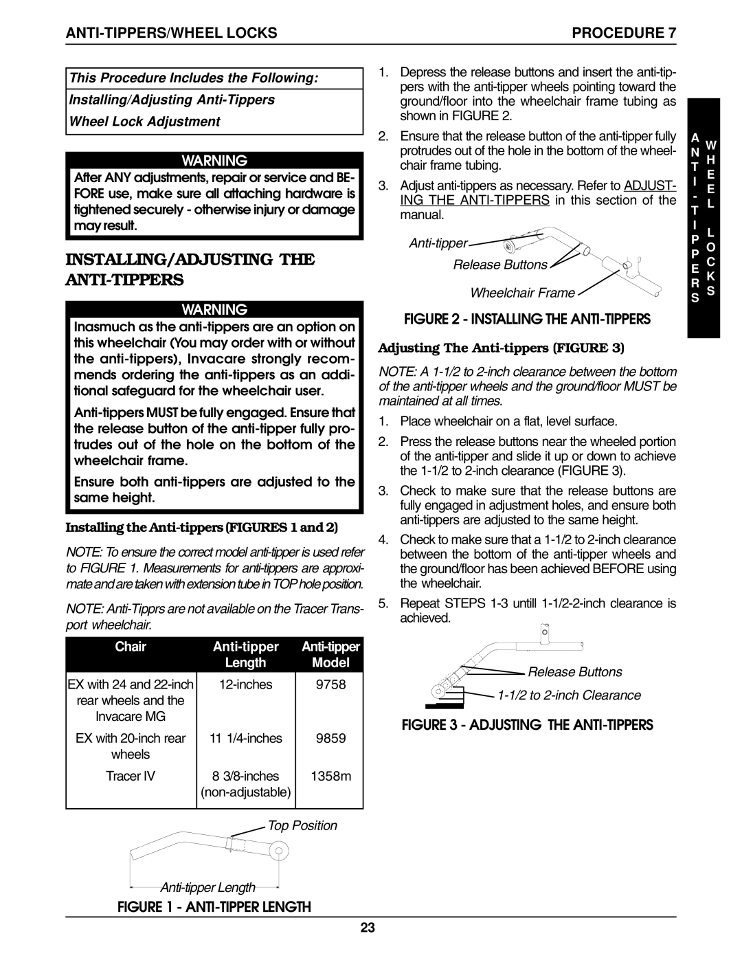
Installing the Anti-tippers (FIGURES 1 and 2)
NOTE: To ensure the correct model
NOTE:
Chair |
| |
| Length | Model |
EX with 24 and | 9758 | |
rear wheels and the |
|
|
Invacare MG |
|
|
EX with | 11 | 9859 |
wheels |
|
|
Tracer IV | 8 | 1358m |
|
| |
|
|
|
| Top Position | |
Anti-tipper Length
FIGURE 1 - ANTI-TIPPER LENGTH
1.Depress the release buttons and insert the
2. Ensure that the release button of the | A | W | |
protrudes out of the hole in the bottom of the wheel- | N | ||
chair frame tubing. | T | H | |
3. Adjust | I | E | |
- | E | ||
ING THE | |||
T | L | ||
manual. | |||
I |
| ||
| L | ||
| P | ||
| P | O | |
Release Buttons | E | C | |
Wheelchair Frame | R | K | |
S | S | ||
|
|
FIGURE 2 - INSTALLING THE ANTI-TIPPERS
Adjusting The Anti-tippers (FIGURE 3)
NOTE: A
1.Place wheelchair on a flat, level surface.
2.Press the release buttons near the wheeled portion of the
3.Check to make sure that the release buttons are fully engaged in adjustment holes, and ensure both
4.Check to make sure that a
5.Repeat STEPS
Release Buttons
FIGURE 3 - ADJUSTING THE ANTI-TIPPERS
23
