SECTION 11—BATTERIES
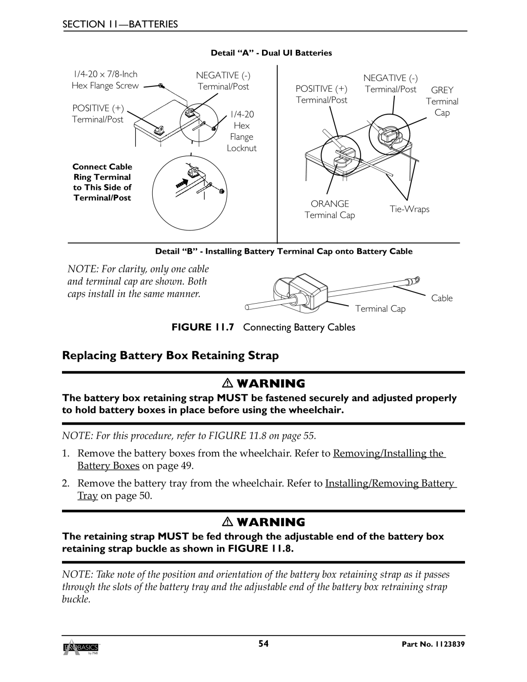
Detail “A” - Dual UI Batteries
NEGATIVE |
| NEGATIVE |
| ||
Hex Flange Screw | Terminal/Post |
|
| ||
POSITIVE (+) | Terminal/Post | GREY | |||
|
| ||||
POSITIVE (+) |
| Terminal/Post |
| Terminal | |
|
| Cap | |||
Terminal/Post |
|
| |||
Hex |
|
|
| ||
|
|
|
| ||
| Flange |
|
|
| |
| Locknut |
|
|
| |
Connect Cable |
|
|
|
| |
Ring Terminal |
|
|
|
| |
to This Side of |
|
|
|
| |
Terminal/Post |
| ORANGE |
|
| |
|
| ||||
|
| Terminal Cap | |||
|
|
|
| ||
Detail “B” - Installing Battery Terminal Cap onto Battery Cable
NOTE: For clarity, only one cable |
|
and terminal cap are shown. Both |
|
caps install in the same manner. | Cable |
| |
Terminal Cap |
|
FIGURE 11.7 Connecting Battery Cables |
|
Replacing Battery Box Retaining Strap
WARNING
The battery box retaining strap MUST be fastened securely and adjusted properly to hold battery boxes in place before using the wheelchair.
NOTE: For this procedure, refer to FIGURE 11.8 on page 55.
1.Remove the battery boxes from the wheelchair. Refer to Removing/Installing the Battery Boxes on page 49.
2.Remove the battery tray from the wheelchair. Refer to Installing/Removing Battery Tray on page 50.
WARNING
The retaining strap MUST be fed through the adjustable end of the battery box retaining strap buckle as shown in FIGURE 11.8.
NOTE: Take note of the position and orientation of the battery box retaining strap as it passes through the slots of the battery tray and the adjustable end of the battery box retraining strap buckle.
54 | Part No. 1123839 |