GCE800W6 specifications
The IOGear GCE800W6 is an advanced KVM (Keyboard, Video, and Mouse) switch that allows users to control multiple computers with a single set of peripherals, enhancing workflow efficiency and reducing desk clutter. This device is particularly useful for environments where multiple systems need to be operated simultaneously, such as in IT departments, data centers, or for users who need to manage multiple workstations.One of the main features of the GCE800W6 is its ability to connect up to eight computers through a single control interface. This is achieved through the use of industry-standard cables, which allows for a streamlined workspace. The KVM switch supports a wide array of operating systems, including Windows, macOS, and Linux, ensuring compatibility regardless of the user's system preference.
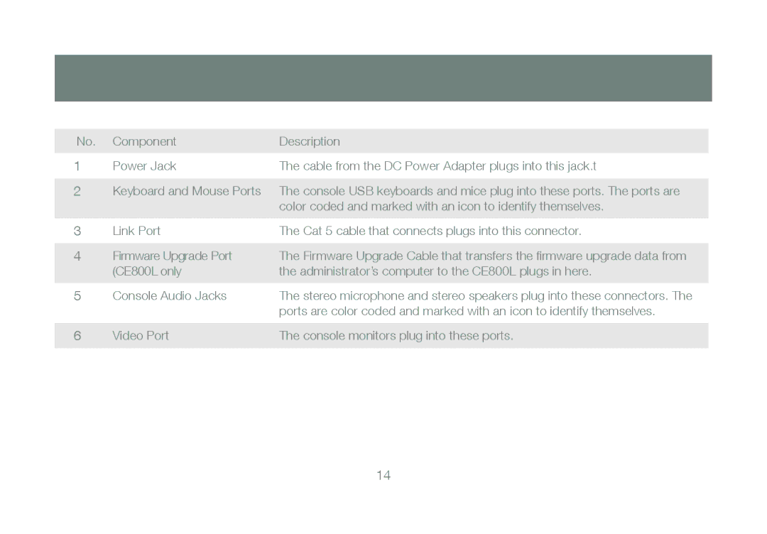
The GCE800W6 utilizes a robust USB interface for both keyboard and mouse connections, making it user-friendly and versatile. It supports full HD video resolutions up to 1920x1200, which ensures that users receive high-quality visuals without compromise. This characteristic is essential for tasks that require detailed graphic work or when high-resolution displays are used.
Another standout feature of this KVM switch is its functionality with both hotkey and physical button switching, providing flexibility for users in how they operate the device. Hotkey switching allows users to toggle between computers quickly, while the physical button provides a more tactile experience for those who prefer manual control. The built-in LED indicators help users easily identify which system is currently active, streamlining the overall usability of the device.
In terms of performance, the GCE800W6 is designed with advanced technologies to minimize latency and enhance the user experience. It supports USB 1.1 and 2.0 compatibility, ensuring that a wide range of peripherals can be utilized. The switch is also equipped with a compact and durable chassis, making it suitable for desktop use as well as for deployment in server racks.
In conclusion, the IOGear GCE800W6 KVM switch is a powerful tool for users requiring efficient management of multiple computers. With its impressive capabilities, including support for high-definition video, versatile connection options, and user-friendly features, it is an essential addition to any multi-computer workstation. Whether for personal use, small businesses, or large enterprises, the GCE800W6 offers reliability and functionality that meets a diverse array of needs.

