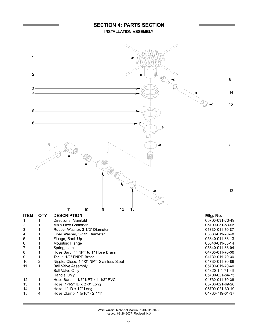
Whirl Wizard specifications
Jackson Whirl Wizard is a dynamic and innovative product that has captivated the market with its unique features and advanced technologies. Designed for versatility and excellence, the Whirl Wizard is primarily targeted at both professional users and hobbyists who require high performance while engaging in a range of activities.One of the defining characteristics of the Jackson Whirl Wizard is its robust design. Built with high-quality materials, it ensures durability and longevity, making it perfect for both indoor and outdoor use. This resilience does not compromise the product's lightweight nature, allowing users to easily transport it wherever they go.
The core technology of the Whirl Wizard lies in its powerful motor. This motor provides an impressive speed range, allowing users to customize their experience based on their needs. Whether it's for precision tasks or high-speed applications, the Whirl Wizard can adapt effectively. Its energy-efficient design also ensures minimal power consumption without sacrificing performance.
Another significant feature of the Jackson Whirl Wizard is its intuitive control system. Users can effortlessly switch between modes and adjust settings through a user-friendly interface. This accessibility makes it suitable for individuals of all skill levels, from beginners to experts, enabling everyone to harness its full potential.
Safety is a paramount concern for Jackson, and the Whirl Wizard reflects this commitment. Equipped with advanced safety features such as automatic shut-off and overload protection, users can operate the device with peace of mind, confident that they are protected from potential hazards.
The Whirl Wizard also includes a variety of attachments that enhance its functionality. These accessories can be easily swapped out, enabling users to tackle different tasks efficiently, such as mixing, blending, and even crafting. The versatility offered by these attachments is one of the key reasons why users praise this product.
In conclusion, the Jackson Whirl Wizard stands out in the market due to its combination of robust design, advanced motor technology, user-friendly controls, and a commitment to safety. Its versatility makes it an ideal choice for those seeking reliability and performance in their projects, whether casual or professional. With the Jackson Whirl Wizard, users are empowered to unleash their creativity and achieve exceptional results in their tasks.

