CV-A1
6.2. Input-output of HD/VD Signals
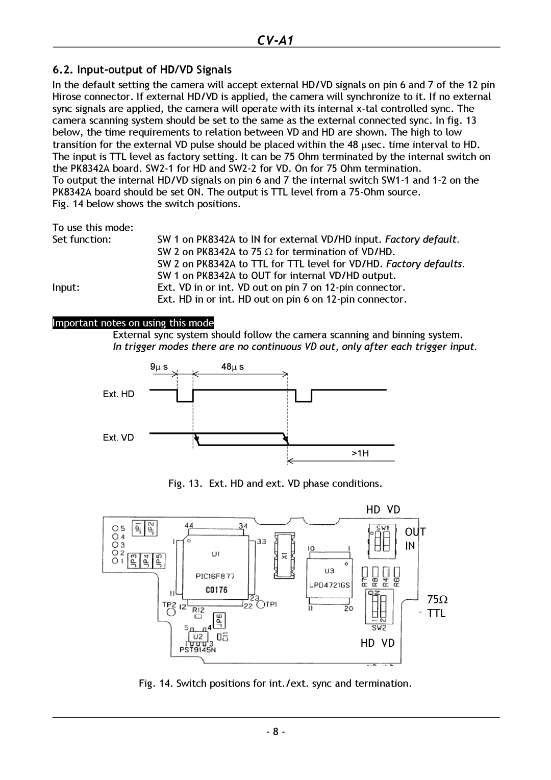
In the default setting the camera will accept external HD/VD signals on pin 6 and 7 of the 12 pin Hirose connector. If external HD/VD is applied, the camera will synchronize to it. If no external sync signals are applied, the camera will operate with its internal
To output the internal HD/VD signals on pin 6 and 7 the internal switch
Fig. 14 below shows the switch positions.
To use this mode: |
|
Set function: | SW 1 on PK8342A to IN for external VD/HD input. Factory default. |
| SW 2 on PK8342A to 75 Ω for termination of VD/HD. |
| SW 2 on PK8342A to TTL for TTL level for VD/HD. Factory defaults. |
| SW 1 on PK8342A to OUT for internal VD/HD output. |
Input: | Ext. VD in or int. VD out on pin 7 on |
| Ext. HD in or int. HD out on pin 6 on |
Important notes on using this mode
External sync system should follow the camera scanning and binning system.
In trigger modes there are no continuous VD out, only after each trigger input.
9∝ s | 48∝ s |
Ext. HD
Ext. VD
>1H
Fig. 13. Ext. HD and ext. VD phase conditions.
HD VD
OUT
IN
75Ω TTL
HD VD
Fig. 14. Switch positions for int./ext. sync and termination.
- 8 -
