See Fig. 16 for the phase relationship between ext. HD and ext. VD pulses.
- 14 -
TR=3
FR=0
SC=1
Trigger mode to “Frame delay read-out” Accumulation to “Field”
Scanning to “Non-interlaced” Polarity and other functions
Ext. trigger to pin 5 on 6 pin connector (or pin 11 on 12 pin connector). Ext. VD to pin 7 on 12 pin connector.
Ext HD to pin 6 on 12 pin connector. (If used)
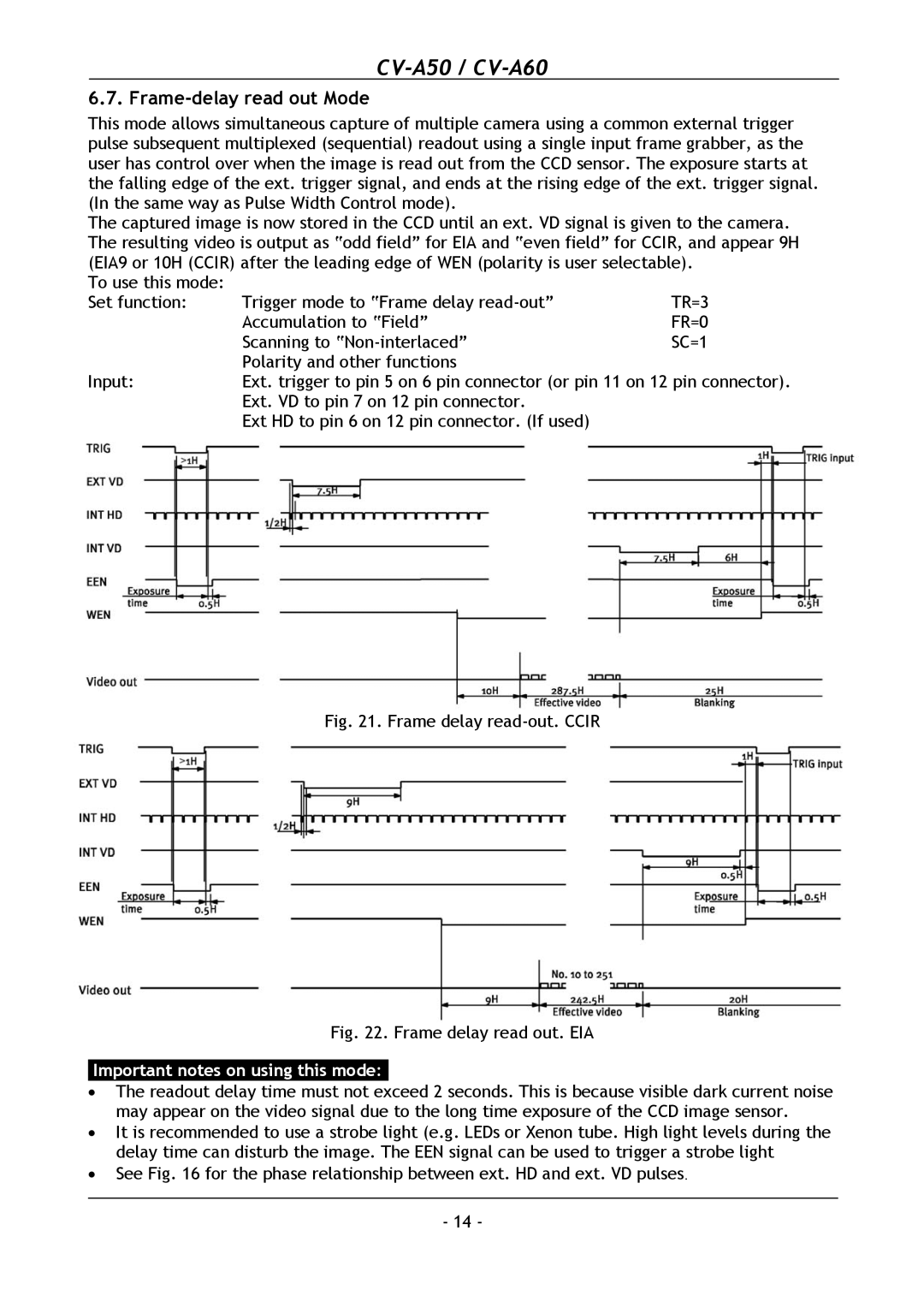
Fig. 21. Frame delay read-out. CCIR
Fig. 22. Frame delay read out. EIA
Important notes on using this mode:-
• The readout delay time must not exceed 2 seconds. This is because visible dark current noise may appear on the video signal due to the long time exposure of the CCD image sensor.
• It is recommended to use a strobe light (e.g. LEDs or Xenon tube. High light levels during the delay time can disturb the image. The EEN signal can be used to trigger a strobe light
Input:
This mode allows simultaneous capture of multiple camera using a common external trigger pulse subsequent multiplexed (sequential) readout using a single input frame grabber, as the user has control over when the image is read out from the CCD sensor. The exposure starts at the falling edge of the ext. trigger signal, and ends at the rising edge of the ext. trigger signal. (In the same way as Pulse Width Control mode).
The captured image is now stored in the CCD until an ext. VD signal is given to the camera. The resulting video is output as “odd field” for EIA and “even field” for CCIR, and appear 9H (EIA9 or 10H (CCIR) after the leading edge of WEN (polarity is user selectable).
To use this mode: Set function:
6.7. Frame-delay read out Mode
•