CV-A50 / CV-A60
6.6. Pulse Width Control Mode
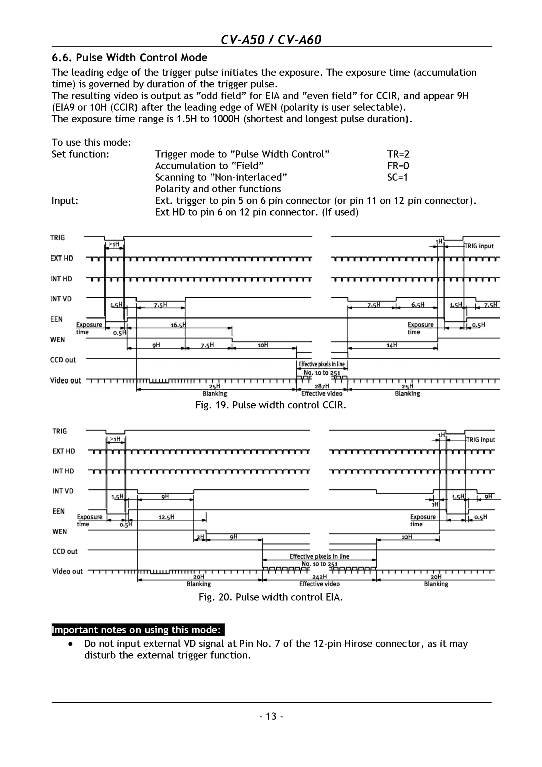
The leading edge of the trigger pulse initiates the exposure. The exposure time (accumulation time) is governed by duration of the trigger pulse.
The resulting video is output as “odd field” for EIA and “even field” for CCIR, and appear 9H (EIA9 or 10H (CCIR) after the leading edge of WEN (polarity is user selectable).
The exposure time range is 1.5H to 1000H (shortest and longest pulse duration).
To use this mode: |
|
|
Set function: | Trigger mode to “Pulse Width Control” | TR=2 |
| Accumulation to “Field” | FR=0 |
| Scanning to | SC=1 |
| Polarity and other functions |
|
Input: | Ext. trigger to pin 5 on 6 pin connector (or pin 11 on 12 pin connector). | |
| Ext HD to pin 6 on 12 pin connector. (If used) |
|
Fig. 19. Pulse width control CCIR.
Fig. 20. Pulse width control EIA.
Important notes on using this mode:-
•Do not input external VD signal at Pin No. 7 of the
-13 -
