|
|
|
|
|
|
| |
|
|
|
|
|
|
| |
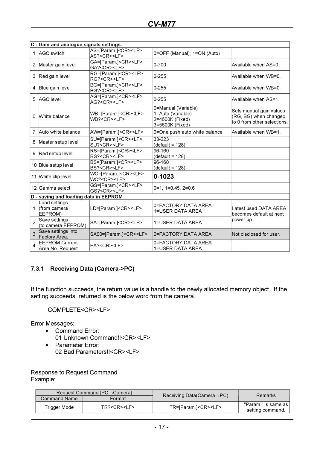
C - Gain and analogue signals settings. |
|
|
|
| |||
1 | AGC switch | AS=[Param.]<CR><LF> |
| 0=OFF (Manual), 1=ON (Auto) |
|
| |
AS?<CR><LF> |
|
|
| ||||
|
|
|
|
|
|
| |
2 | Master gain level | GA=[Param.]<CR><LF> |
| Available when AS=0. |
| ||
GA?<CR><LF> |
|
| |||||
|
|
|
|
|
|
| |
3 | Red gain level | RG=[Param.]<CR><LF> |
| Available when WB=0. |
| ||
RG?<CR><LF> |
|
| |||||
|
|
|
|
|
|
| |
4 | Blue gain level | BG=[Param.]<CR><LF> |
| Available when WB=0. |
| ||
BG?<CR><LF> |
|
| |||||
|
|
|
|
|
|
| |
5 | AGC level | AG=[Param.]<CR><LF> |
| Available when AS=1. |
| ||
AG?<CR><LF> |
|
| |||||
|
|
|
|
|
|
| |
|
|
| WB=[Param.]<CR><LF> |
| 0=Manual (Variable) | Sets manual gain values |
|
|
|
|
| 1=Auto (Variable) |
| ||
6 | White balance |
| (RG, BG) when changed |
| |||
WB?<CR><LF> |
| 2=4600K (Fixed) |
| ||||
|
|
|
| to 0 from other selections. |
| ||
|
|
|
|
| 3=5600K (Fixed) |
| |
|
|
|
|
|
|
| |
7 | Auto white balance | AW=[Param.]<CR><LF> |
| 0=One push auto white balance | Available when WB=1. |
| |
|
|
|
|
|
|
|
|
8 | Master setup level | SU=[Param.]<CR><LF> |
|
|
| ||
SU?<CR><LF> |
| (default = 128) |
|
| |||
|
|
|
|
|
| ||
9 | Red setup level | RS=[Param.]<CR><LF> |
|
|
| ||
RS?<CR><LF> |
| (default = 128) |
|
| |||
|
|
|
|
|
| ||
10 | Blue setup level | BS=[Param.]<CR><LF> |
|
|
| ||
BS?<CR><LF> |
| (default = 128) |
|
| |||
|
|
|
|
|
| ||
11 | White clip level | WC=[Param.]<CR><LF> |
|
|
|
| |
WC?<CR><LF> |
|
|
| ||||
12 | Gamma select | GS=[Param.]<CR><LF> |
| 0=1, 1=0.45, 2=0.6 |
|
| |
GS?<CR><LF> |
|
|
| ||||
|
|
|
|
|
|
| |
D - | saving and loading data in EEPROM |
|
|
|
| ||
|
| Load settings |
|
| 0=FACTORY DATA AREA |
|
|
1 | (from camera | LD=[Param.]<CR><LF> |
| Latest used DATA AREA |
| ||
| 1=USER DATA AREA |
| |||||
|
| EEPROM) |
|
| becomes default at next |
| |
|
|
|
|
|
| ||
2 | Save settings | SA=[Param.]<CR><LF> |
| 1=USER DATA AREA | power up. |
| |
(to camera EEPROM) |
|
|
| ||||
3 | Save settings into | SA00=[Param.]<CR><LF> |
| 0=FACTORY DATA AREA | Not disclosed for user. |
| |
Factory Area. |
|
| |||||
|
|
|
|
| |||
4 | EEPROM Current | EA?<CR><LF> |
| 0=FACTORY DATA AREA |
|
| |
|
| Area No. Request |
|
| 1=USER DATA AREA |
|
|
7.3.1Receiving Data (Camera->PC)
If the function succeeds, the return value is a handle to the newly allocated memory object. If the setting succeeds, returned is the below word from the camera.
COMPLETE<CR><LF>
Error Messages:
•Command Error:
01Unknown Command!!<CR><LF>
•Parameter Error:
02Bad Parameters!!<CR><LF>
Response to Request Command
Example:
| Request Command (PC→Camera) | Receiving Data(Camera→PC) | Remarks |
| |
| Command Name | Format |
| ||
|
|
|
| ||
| Trigger Mode | TR?<CR><LF> | TR=[Param.]<CR><LF> | "Param." is same as |
|
| setting command. |
| |||
|
|
|
|
| |
|
|
|
|
|
|
|
|
| - 17 - |
|
|