CV-M77
5 Pin Assignment
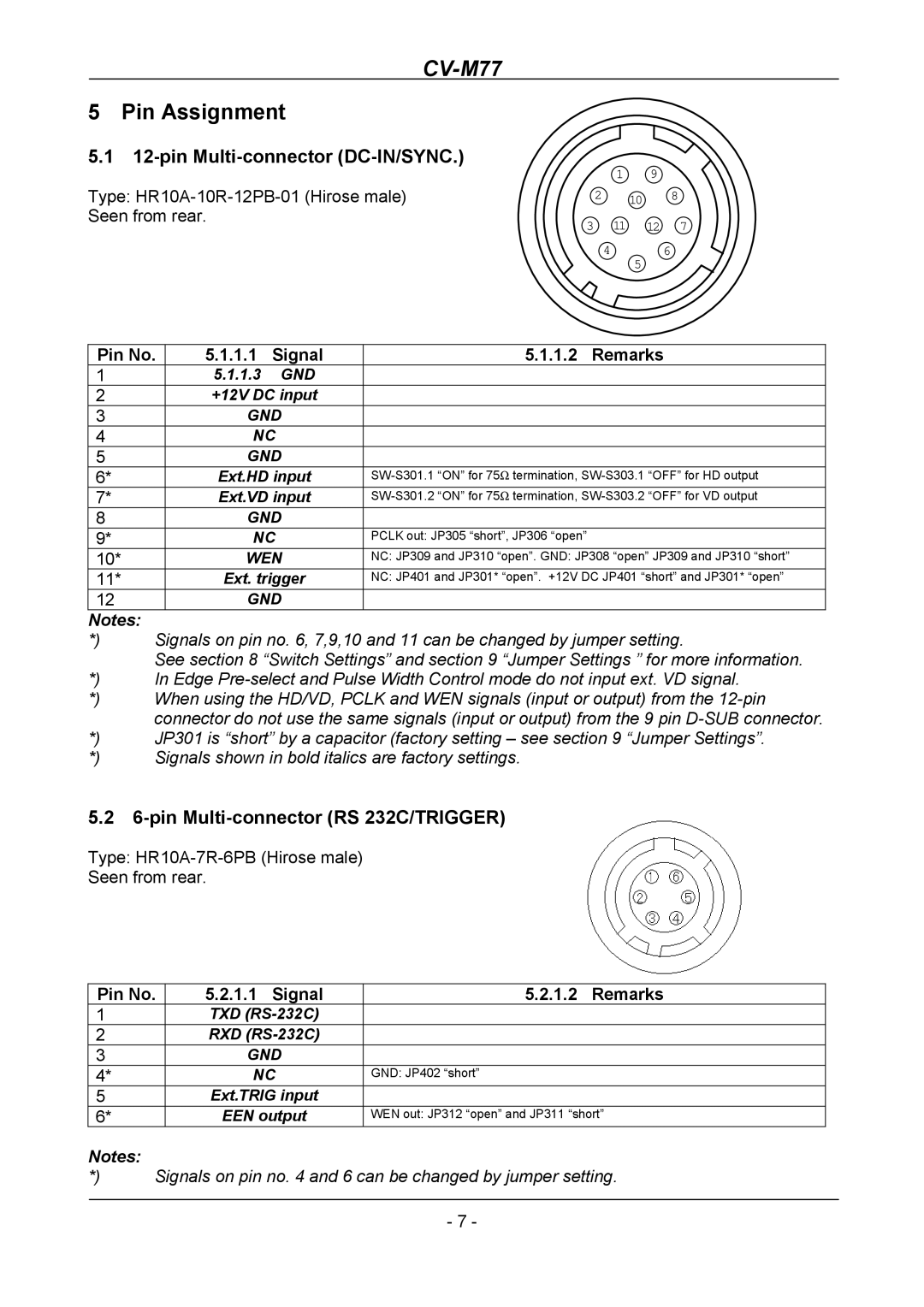
5.112-pin Multi-connector (DC-IN/SYNC.)
Type:
1 9
2 10 8
3 11 12 7
46
5
Pin No. | 5.1.1.1 | Signal | 5.1.1.2 Remarks | |
1 |
| 5.1.1.3 | GND |
|
2 |
| +12V DC input |
| |
3 |
| GND |
| |
4 |
| NC |
| |
5 |
| GND |
| |
6* |
| Ext.HD input | ||
7* |
| Ext.VD input | ||
8 |
| GND |
| |
9* |
| NC | PCLK out: JP305 “short”, JP306 “open” | |
10* |
| WEN | NC: JP309 and JP310 “open”. GND: JP308 “open” JP309 and JP310 “short” | |
11* |
| Ext. trigger | NC: JP401 and JP301* “open”. +12V DC JP401 “short” and JP301* “open” | |
12 |
| GND |
| |
Notes: |
|
|
|
|
*) | Signals on pin no. 6, 7,9,10 and 11 can be changed by jumper setting. | |||
| See section 8 “Switch Settings” and section 9 “Jumper Settings ” for more information. | |||
*) | In Edge | |||
*) | When using the HD/VD, PCLK and WEN signals (input or output) from the | |||
| connector do not use the same signals (input or output) from the 9 pin | |||
*) | JP301 is “short” by a capacitor (factory setting – see section 9 “Jumper Settings”. | |||
*) | Signals shown in bold italics are factory settings. | |||
5.26-pin Multi-connector (RS 232C/TRIGGER)
Type:
Seen from rear.
Pin No. | 5.2.1.1 Signal | 5.2.1.2 Remarks |
| |
1 |
| TXD |
|
|
2 |
| RXD |
|
|
3 |
| GND |
|
|
4* |
| NC | GND: JP402 “short” |
|
5 |
| Ext.TRIG input |
|
|
6* |
| EEN output | WEN out: JP312 “open” and JP311 “short” |
|
Notes: |
|
|
|
|
*) | Signals on pin no. 4 and 6 can be changed by jumper setting. | |||
|
|
|
|
|
|
|
| - 7 - |
|