C.1. Parallel Interface
Interface Signals
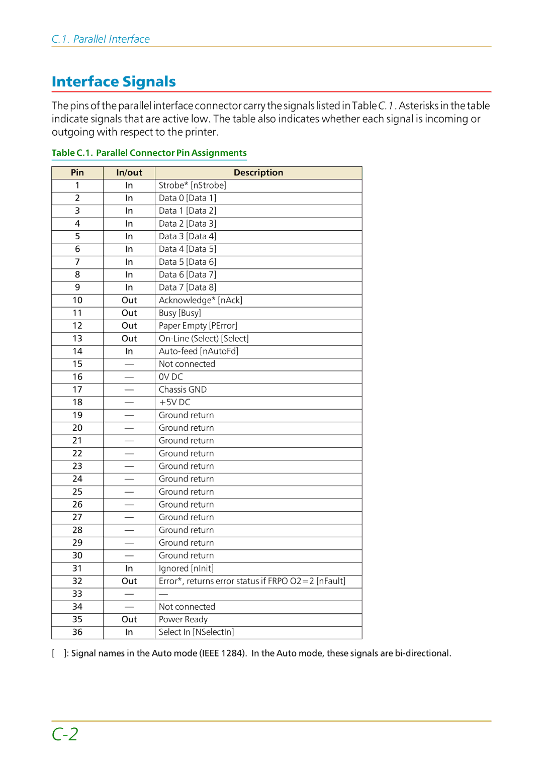
The pins of the parallel interface connector carry the signals listed in Table C.1. Asterisks in the table indicate signals that are active low. The table also indicates whether each signal is incoming or outgoing with respect to the printer.
Table C.1. Parallel Connector Pin Assignments
Pin | In/out | Description |
1 | In | Strobe* [nStrobe] |
|
|
|
2 | In | Data 0 [Data 1] |
|
|
|
3 | In | Data 1 [Data 2] |
|
|
|
4 | In | Data 2 [Data 3] |
|
|
|
5 | In | Data 3 [Data 4] |
|
|
|
6 | In | Data 4 [Data 5] |
|
|
|
7 | In | Data 5 [Data 6] |
|
|
|
8 | In | Data 6 [Data 7] |
|
|
|
9 | In | Data 7 [Data 8] |
|
|
|
10 | Out | Acknowledge* [nAck] |
|
|
|
11 | Out | Busy [Busy] |
|
|
|
12 | Out | Paper Empty [PError] |
|
|
|
13 | Out | |
|
|
|
14 | In | |
|
|
|
15 | — | Not connected |
|
|
|
16 | — | 0V DC |
|
|
|
17 | — | Chassis GND |
|
|
|
18 | — | +5V DC |
|
|
|
19 | — | Ground return |
|
|
|
20 | — | Ground return |
|
|
|
21 | — | Ground return |
|
|
|
22 | — | Ground return |
|
|
|
23 | — | Ground return |
|
|
|
24 | — | Ground return |
|
|
|
25 | — | Ground return |
|
|
|
26 | — | Ground return |
|
|
|
27 | — | Ground return |
|
|
|
28 | — | Ground return |
|
|
|
29 | — | Ground return |
|
|
|
30 | — | Ground return |
|
|
|
31 | In | Ignored [nInit] |
|
|
|
32 | Out | Error*, returns error status if FRPO O2=2 [nFault] |
|
|
|
33 | — | — |
|
|
|
34 | — | Not connected |
|
|
|
35 | Out | Power Ready |
|
|
|
36 | In | Select In [NSelectIn] |
|
|
|
[ ]: Signal names in the Auto mode (IEEE 1284). In the Auto mode, these signals are