C.2.
Verifying the Setting
The procedure described below should be followed to verify that the
1.Make sure the power switch is off. Plug the power cord into the printer and turn power on.
2. If the printer is
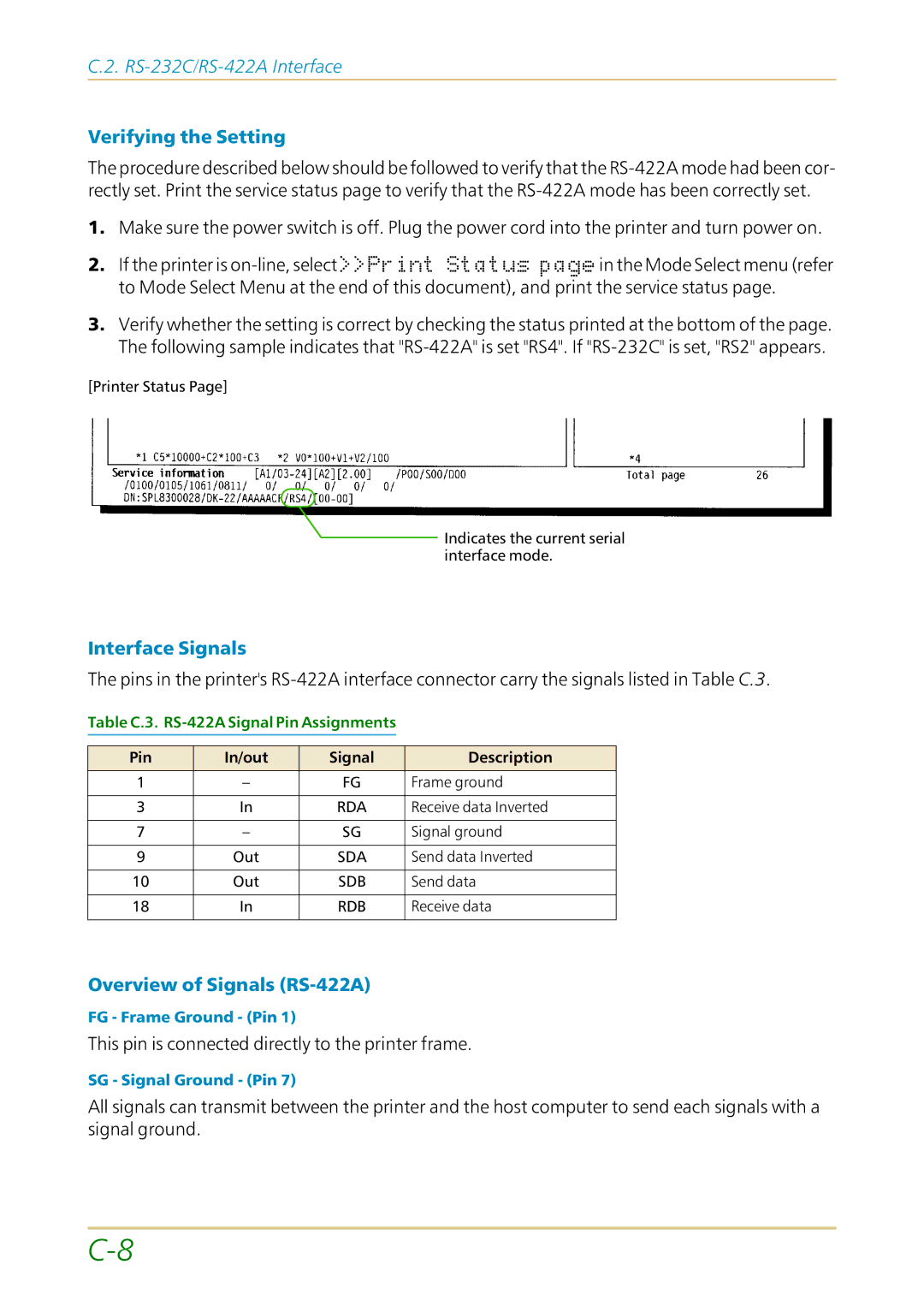
3.Verify whether the setting is correct by checking the status printed at the bottom of the page. The following sample indicates that
[Printer Status Page]
![]() Indicates the current serial interface mode.
Indicates the current serial interface mode.
Interface Signals
The pins in the printer's
Table C.3. RS-422A Signal Pin Assignments
Pin | In/out | Signal | Description |
1 | – | FG | Frame ground |
|
|
|
|
3 | In | RDA | Receive data Inverted |
|
|
|
|
7 | – | SG | Signal ground |
|
|
|
|
9 | Out | SDA | Send data Inverted |
|
|
|
|
10 | Out | SDB | Send data |
|
|
|
|
18 | In | RDB | Receive data |
|
|
|
|
Overview of Signals (RS-422A)
FG - Frame Ground - (Pin 1)
This pin is connected directly to the printer frame.
SG - Signal Ground - (Pin 7)
All signals can transmit between the printer and the host computer to send each signals with a signal ground.