|
|
| See section 8 “Switch Settings” and section 9 “Jumper Settings ” for more information. |
*) | When using the WEN signal from the 6 pin connector do not use the same signal from the |
| 9 pin connector. |
*) | Signals shown in bold italics are factory settings. |
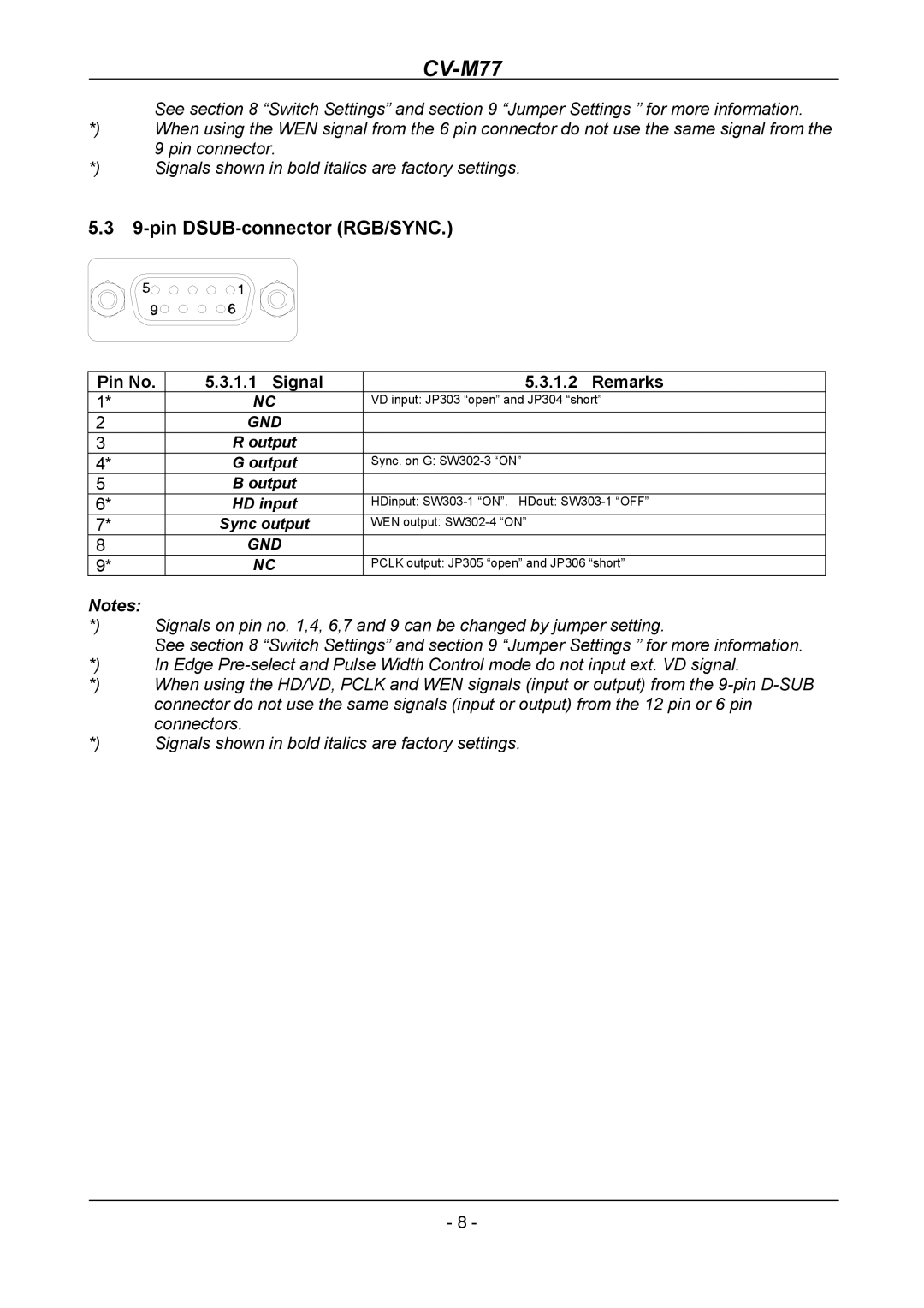
5.39-pin DSUB-connector (RGB/SYNC.)
Pin No. | 5.3.1.1 Signal | 5.3.1.2 Remarks |
1* | NC | VD input: JP303 “open” and JP304 “short” |
2 | GND |
|
3 | R output |
|
4* | G output | Sync. on G: |
5 | B output |
|
6* | HD input | HDinput: |
7* | Sync output | WEN output: |
8 | GND |
|
9* | NC | PCLK output: JP305 “open” and JP306 “short” |
Notes: |
|
*) | Signals on pin no. 1,4, 6,7 and 9 can be changed by jumper setting. |
| See section 8 “Switch Settings” and section 9 “Jumper Settings ” for more information. |
*) | In Edge |
*) | When using the HD/VD, PCLK and WEN signals (input or output) from the |
| connector do not use the same signals (input or output) from the 12 pin or 6 pin |
| connectors. |
*) | Signals shown in bold italics are factory settings. |
- 8 -