APPLICATIONS – CS200.1
The CS subwoofer amplifiers are
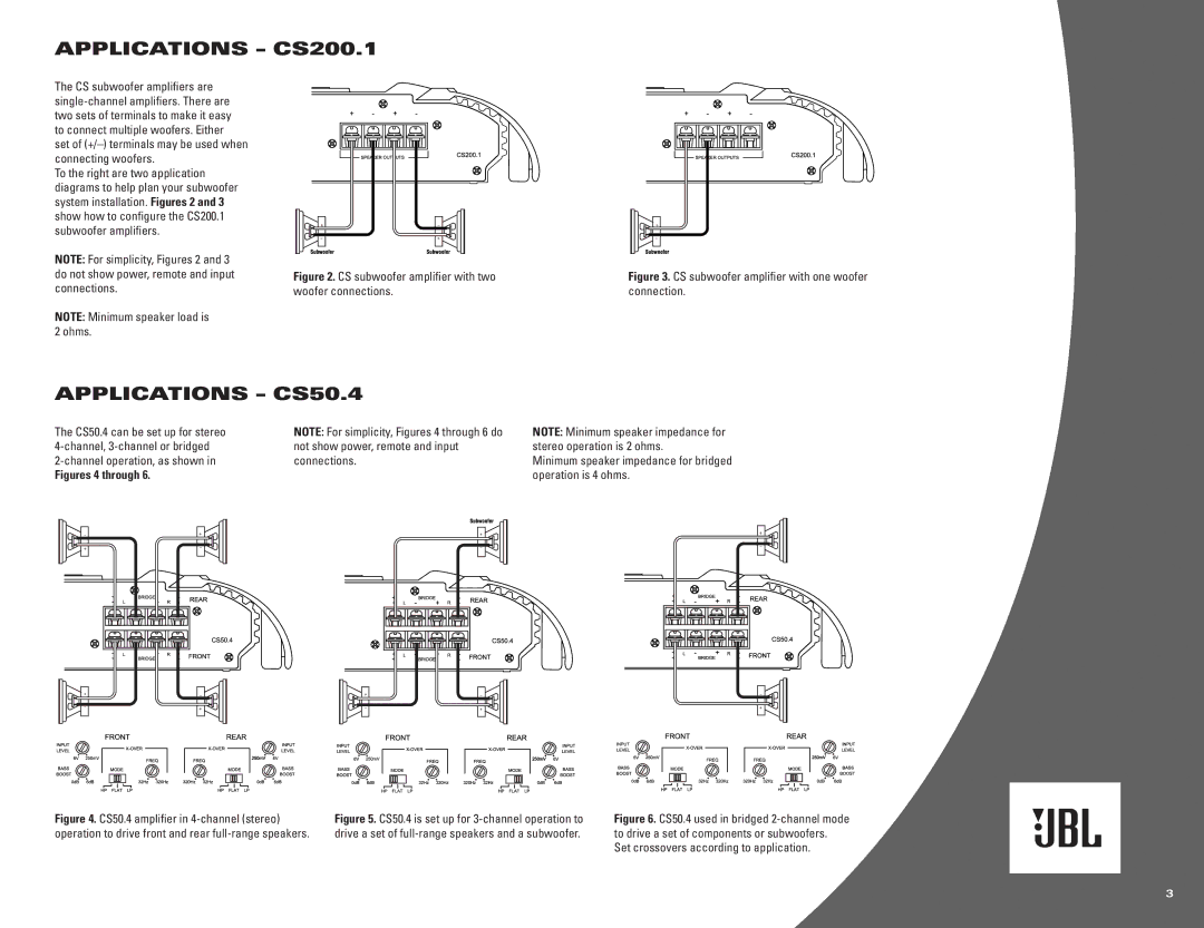
To the right are two application diagrams to help plan your subwoofer system installation. Figures 2 and 3 show how to configure the CS200.1 subwoofer amplifiers.
NOTE: For simplicity, Figures 2 and 3 do not show power, remote and input connections.
NOTE: Minimum speaker load is 2 ohms.
Figure 2. CS subwoofer amplifier with two woofer connections.
Figure 3. CS subwoofer amplifier with one woofer connection.
APPLICATIONS – CS50.4
The CS50.4 can be set up for stereo | NOTE: For simplicity, Figures 4 through 6 do |
not show power, remote and input | |
connections. | |
Figures 4 through 6. |
|
NOTE: Minimum speaker impedance for stereo operation is 2 ohms.
Minimum speaker impedance for bridged operation is 4 ohms.
Figure 4. CS50.4 amplifier in 4-channel (stereo) operation to drive front and rear full-range speakers.
Figure 5. CS50.4 is set up for 3-channel operation to drive a set of full-range speakers and a subwoofer.
Figure 6. CS50.4 used in bridged 2-channel mode to drive a set of components or subwoofers.
Set crossovers according to application.
3
