GTH400-20107 06/03/98 15:49 Side 12
4.2 Internal Adjustments
Impedance Adjustments
The speaker level inputs of the GTH400 come factory set with 100k ohm input impedance. This will provide the lowest distortion operation from the speaker outputs of most modern head units by reducing the power the amplifier in the head unit must deliver to practically nothing. On some older, or
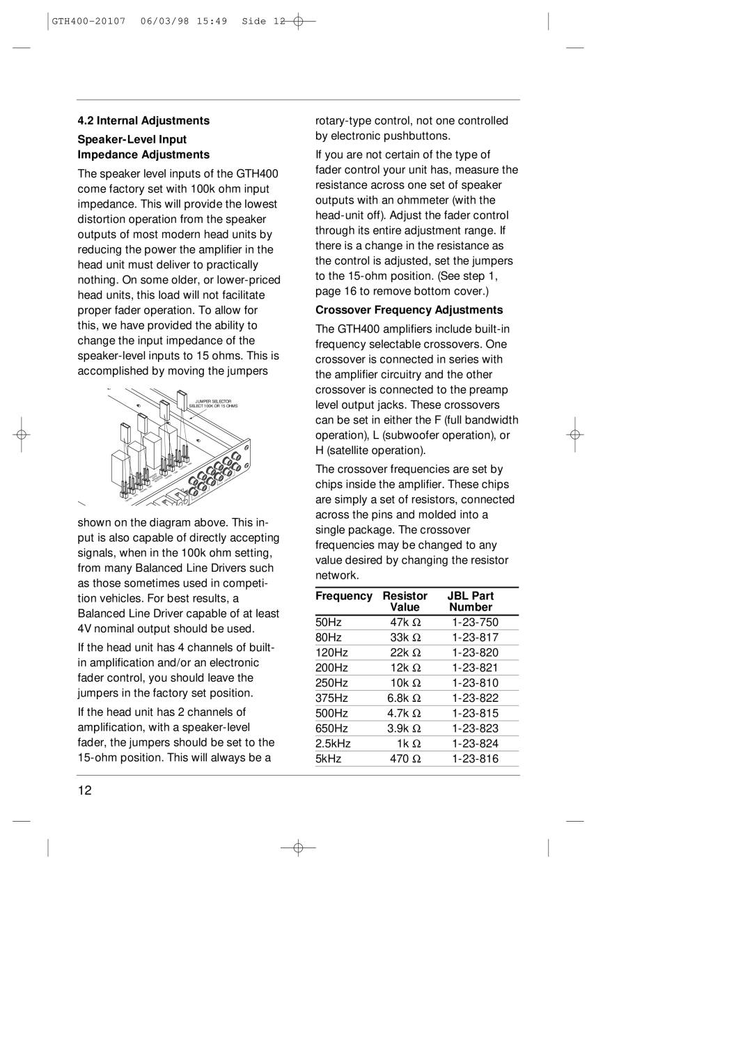
JUMPER SELECTOR
SELECT 100K OR 15 OHMS
|
|
| 150HMS | 100K |
|
|
|
| |
| SPEAKER | 150HMS | 100K |
|
|
| LINE | ||
| INPUT |
| INPUT | |
| IMPEDANCESELECTOR |
|
|
|
150HMS | 100K |
|
|
|
|
|
| PREAMP | |
100K |
|
|
| OUT |
150HMS |
|
|
|
|
shown on the diagram above. This in- put is also capable of directly accepting signals, when in the 100k ohm setting, from many Balanced Line Drivers such as those sometimes used in competi- tion vehicles. For best results, a Balanced Line Driver capable of at least 4V nominal output should be used.
If the head unit has 4 channels of built- in amplification and/or an electronic fader control, you should leave the jumpers in the factory set position.
If the head unit has 2 channels of amplification, with a
12
If you are not certain of the type of fader control your unit has, measure the resistance across one set of speaker outputs with an ohmmeter (with the
Crossover Frequency Adjustments
The GTH400 amplifiers include
The crossover frequencies are set by chips inside the amplifier. These chips are simply a set of resistors, connected across the pins and molded into a single package. The crossover frequencies may be changed to any value desired by changing the resistor network.
Frequency | Resistor | JBL Part | |
| Value | Number | |
50Hz | 47k | Ω | |
80Hz | 33k | Ω | |
120Hz | 22k | Ω | |
200Hz | 12k | Ω | |
250Hz | 10k | Ω | |
375Hz | 6.8k | Ω | |
500Hz | 4.7k | Ω | |
650Hz | 3.9k | Ω | |
2.5kHz | 1k | Ω | |
5kHz | 470 | Ω | |