GTH400-20107 06/03/98 15:49 Side 16
is heat- and
insulated
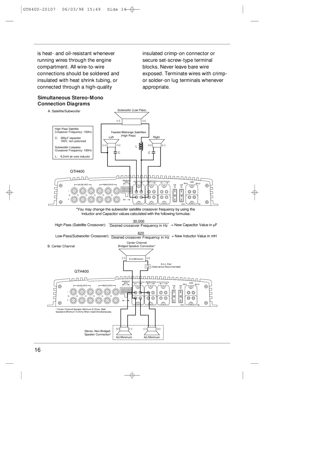
Simultaneous Stereo-Mono
Connection Diagrams
A. Satellite/Subwoofer | Subwoofer |
High Pass Satellite Crossover Frequency: 100Hz
C:300∝F capacitor 100V,
Subwoofer Lowpass Crossover Frequency: 100Hz
L:6.2mH air core inductor
| (+) |
|
| |
| Tweeter/Midrange Satellites |
|
| |
| Left | (High Pass) |
| Right |
|
|
| ||
(+) | L | (+) | ||
|
|
|
| |
| C |
| C |
|
GTH400
|
|
|
|
| SPEAKER LEVEL | L | 1 | R | SPEAKER OUTPUTS | L | 3 | R | |||||
|
|
|
|
| R | INPUTS | L | L | 2 | R | |||||||
| LINE LEVEL INPUTS |
|
| PREAMP OUTPUTS | – | 2 | + |
| + | + |
| + | + |
| + | ||
|
|
| + | – | + |
|
|
|
|
|
|
|
|
| |||
1 | 2 | 3 | 1 | 2 | 3 |
|
|
|
|
|
|
|
|
|
|
|
|
L |
|
|
|
|
|
|
|
|
|
|
|
|
|
|
|
| + |
|
|
|
|
|
|
|
|
|
|
|
|
|
|
|
|
| |
+ | – | – | + |
|
| – |
R | R | 1 | L |
|
|
|
|
|
| _ | _ | _ | _ |
POWER
FUSE | REM IN | REM OUT |
FUSE |
| |
30A | 30A |
|
30A | 30A |
|
| BATT(+) | GND |
*You may change the subwoofer satellite crossover frequency by using the Inductor and Capacitor values calculated with the following formulas:
|
|
| 30,000 |
|
|
|
| = New Capacitor Value in ∝F | |
Desired crossover Frequency in Hz |
|
| |||||||
|
| 620 |
|
|
|
| = New Inductor Value in mH | ||
Desired crossover Frequency in Hz |
| ||||||||
B. Center Channel |
|
| Center Channel |
| |||||
| Bridged Speaker Connection* |
| |||||||
|
|
|
| (+) |
|
|
|
| |
|
| 8 | Ω Minimum |
|
|
|
| ||
|
|
|
|
|
|
|
| ||
|
|
|
|
|
| 8 Ω |
| ||
|
|
|
|
|
|
| |||
|
|
|
|
|
| (Optional but Recommended) | |||
GTH400
| LINE LEVEL INPUTS |
|
|
| PREAMP OUTPUTS |
|
|
|
|
|
| ||
1 | 2 | 3 | 1 | 2 | 3 | |
L
R
*Center Channel Speaker Minimum 8 Ohms, Main Speakers Minimum 4 Ohms When Used Simultaneously.
SPEAKER LEVEL |
| L | 1 | R | SPEAKER OUTPUTS | L | 3 | R |
|
| POWER | |||||
R | INPUTS |
| + | L | 2 | R |
| REM IN | ||||||||
2 | L | + |
|
| + | + |
| + | + |
| + | FUSE | REM OUT | |||
+ | – | – |
|
|
|
|
|
|
|
|
|
| FUSE |
| ||
|
|
|
|
|
|
|
|
|
|
|
|
|
| 30A | 30A |
|
|
|
|
|
| + |
|
|
|
+ – | – | + |
|
| – | 30A | 30A |
|
|
|
|
|
| ||||
R | 1 | L |
|
|
|
|
|
|
|
| _ | _ | _ | _ |
| BATT(+) | GND |
Stereo,
(+)
4Ω
|
| (+) | ||
Minimum | 4Ω Minimum | |||
16