Specifications:
System:
Frequency Response
Low Frequency Extension: User controls set to default
Enclosure Resonance Frequency: 28 Hz
Distortion, 96 dB SPL/ 1 m: Low Frequency (<80 Hz):
2nd Harmonic: <2%
3rd Harmonic: <1%
Maximum Continuous SPL: >112 dB SPL / 1 m (35 Hz - 80 Hz)
Maximum Peak SPL: >115 dB SPL / 1 m (35 Hz - 80 Hz)
Calibrated Input Sensitivity:
XLR or ¼",
Selectable
Power Nonlinearity (20 Hz – 200 Hz):
30 Watts: <0.4 dB
100 Watts: <1.0 dB
Power/Clip/Bypass Indicators: Green LED – normal operation
Amber LED – bypass mode
Red LED – Limiter activated
Amplifier:
Low Frequency Topology: Class
Sine Wave Power Rating: 260 watts (<0.5% THD into rated impedance)
THD + N, ½ Power: <0.05%
AC Input Voltage: 115 VAC, 60 Hz (230VAC, 50 Hz – model
LSR6312SP/230)
AC Input Voltage Operating Range: ±15%
Transducer:
Low Frequency Model: 252F
Diameter: 300 MM (12 in)
Voice Coil: 50 mm (2 in) Differential Drive® with dynamic braking coil
Magnet Type: Neodymium, with integral heat sink
Cone Type: Carbon fiber composite
Impedance: 2 ohms
User Controls, Inputs and Outputs:
Left, Center, Right and Direct Inputs: Neutrik Combi
Left, Center and Right Outputs: Neutrik XLR, balanced (pin 2 hot)
Low Frequency Summed Output: Neutrik XLR, balanced (pin 2 hot)
Remote Bypass Connector: ¼"
Direct Input LFE +10 dB:
LF Output Trim: 0 to
LF Sensitivity (+4 dBu):
Polarity Reverse: In/Out
LF Alignment: 0,
RMC Defeat: In/Out
Remote RMC Defeat Connector: ¼"
Subwoofer Bypass Connector: ¼"
RMC Frequency Adjust: 35 Hz - 200 Hz (21 centers)
RMC Depth Adjust: 0 - 14 dB (cut only, 21 steps)
RMC Q Adjust: 1/20th to 1/2 Octave (21 steps)
Physical:
Finish: Smooth dark graphite
Enclosure Construction: 19 mm (¾ in) MDF
Mounting: 4 threaded mounting points conforming to industry standard square pattern 127 x 70 mm (5 x 2.75 in) center to center. M6 metric threads.
Baffle Material: Injection molded structural ABS
Enclosure Volume (net): 50 liter (1.8 cu ft)
Net Weight: 22.7 kg (50 lb)
Dimensions (WxHxD): 63.5 x 39.4 x 29.2 cm (25.0 x 15.5 x 11.5 in)
Caution: Unsafe mounting or overhead suspension of any heavy load can result in serious injury and equipment damage. Mounting of speakers should be done by qualified persons in accordance with all applicable local safety and construction standards. Be certain to follow the instructions provided by the manufacturer of the mounting bracket. Before selecting a mount- ing bracket, be certain that it is capable of supporting the weight of the speaker to be mounted.
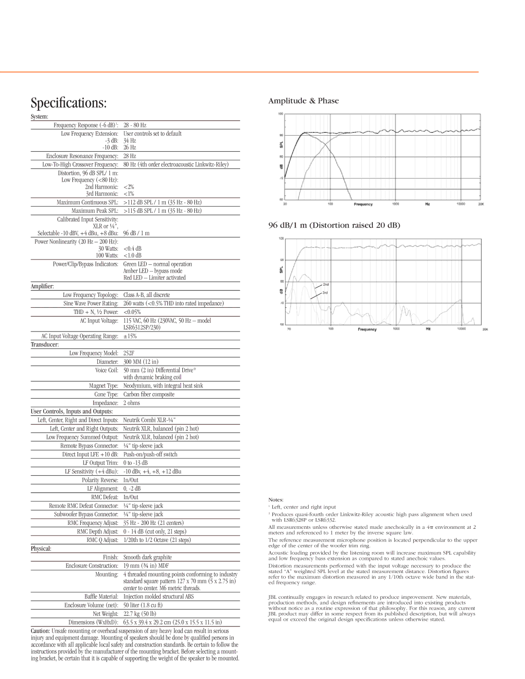
Amplitude & Phase
96 dB/1 m (Distortion raised 20 dB)
2nd
3rd
Notes:
1Left, center and right input
2Produces
All measurements unless otherwise stated made anechoically in a 4 environment at 2 meters and referenced to 1 meter by the inverse square law.
The reference measurement microphone position is located perpendicular to the upper edge of the center of the woofer trim ring.
Acoustic loading provided by the listening room will increase maximum SPL capability and low frequency bass extension as compared to stated anechoic values.
Distortion measurements performed with the input voltage necessary to produce the stated “A” weighted SPL level at the stated measurement distance. Distortion figures refer to the maximum distortion measured in any 1/10th octave wide band in the stat- ed frequency range.
JBL continually engages in research related to produce improvement. New materials, production methods, and design refinements are introduced into existing products without notice as a routine expression of that philosophy. For this reason, any current JBL product may differ in some respect from its published description, but will always equal or exceed the original design specifications unless otherwise stated.
