®
CM715K
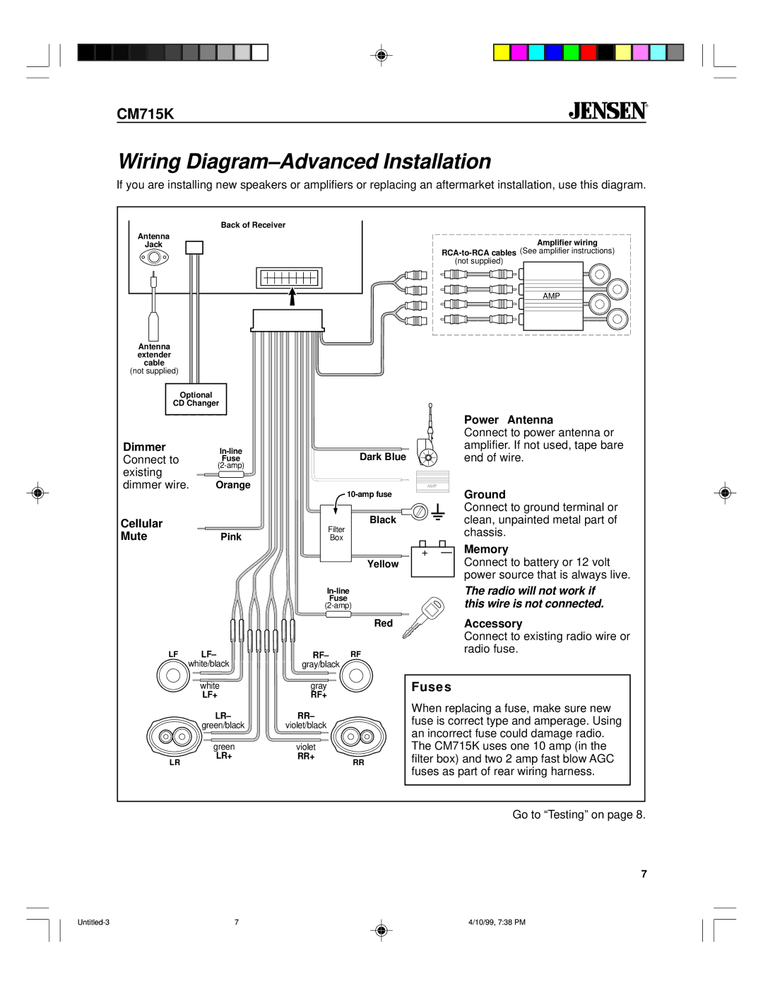
Wiring Diagram–Advanced Installation
If you are installing new speakers or amplifiers or replacing an aftermarket installation, use this diagram.
Back of Receiver
Antenna
Jack
Antenna extender cable
(not supplied)
Amplifier wiring |
(not supplied) |
AMP |
Optional
CD Changer
Dimmer | |
Connect to | Fuse |
existing | |
|
| Power Antenna |
| Connect to power antenna or |
Dark Blue | amplifier. If not used, tape bare |
end of wire. |
dimmer wire. | Orange |
Cellular |
|
Mute | Pink |
LF LF– white/black
Black
Filter
Box
Yellow
Fuse
Red
RF– RF gray/black
AMP
+–
Ground
Connect to ground terminal or clean, unpainted metal part of chassis.
Memory
Connect to battery or 12 volt power source that is always live.
The radio will not work if this wire is not connected.
Accessory
Connect to existing radio wire or radio fuse.
white
LF+
LR–
green/black
green
LR+
LR
gray
RF+
RR–
violet/black
violet
RR+
RR
Fuses
When replacing a fuse, make sure new fuse is correct type and amperage. Using an incorrect fuse could damage radio. The CM715K uses one 10 amp (in the filter box) and two 2 amp fast blow AGC fuses as part of rear wiring harness.
Go to “Testing” on page 8.
7
7 | 4/10/99, 7:38 PM |