4.Before applying final torque, check to make sure the mill head is perpendicular to the worktable.

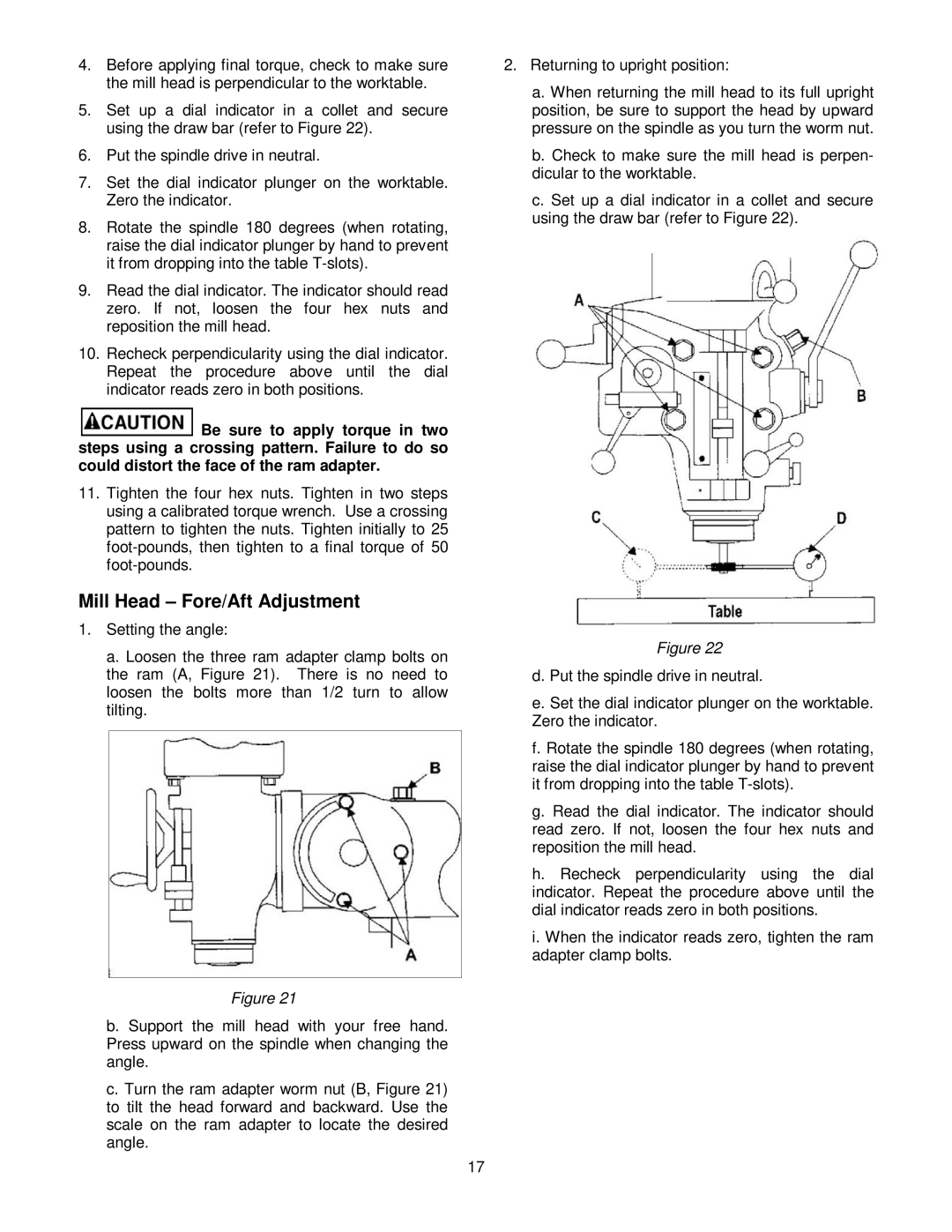
5.Set up a dial indicator in a collet and secure using the draw bar (refer to Figure 22).

6.Put the spindle drive in neutral.

7.Set the dial indicator plunger on the worktable. Zero the indicator.

8.Rotate the spindle 180 degrees (when rotating, raise the dial indicator plunger by hand to prevent it from dropping into the table T-slots).

9.Read the dial indicator. The indicator should read zero. If not, loosen the four hex nuts and reposition the mill head.

10.Recheck perpendicularity using the dial indicator. Repeat the procedure above until the dial indicator reads zero in both positions.

Be sure to apply torque in two steps using a crossing pattern. Failure to do so could distort the face of the ram adapter.

11.Tighten the four hex nuts. Tighten in two steps using a calibrated torque wrench. Use a crossing pattern to tighten the nuts. Tighten initially to 25 foot-pounds, then tighten to a final torque of 50 foot-pounds.

Mill Head – Fore/Aft Adjustment

1.Setting the angle:

a. Loosen the three ram adapter clamp bolts on the ram (A, Figure 21). There is no need to loosen the bolts more than 1/2 turn to allow tilting.

Figure 21

b. Support the mill head with your free hand. Press upward on the spindle when changing the angle.

c. Turn the ram adapter worm nut (B, Figure 21) to tilt the head forward and backward. Use the scale on the ram adapter to locate the desired angle.

2.Returning to upright position:

a.When returning the mill head to its full upright position, be sure to support the head by upward pressure on the spindle as you turn the worm nut.

b.Check to make sure the mill head is perpen- dicular to the worktable.

c.Set up a dial indicator in a collet and secure using the draw bar (refer to Figure 22).

Figure 22

d. Put the spindle drive in neutral.

e. Set the dial indicator plunger on the worktable. Zero the indicator.

f. Rotate the spindle 180 degrees (when rotating, raise the dial indicator plunger by hand to prevent it from dropping into the table T-slots).

g. Read the dial indicator. The indicator should read zero. If not, loosen the four hex nuts and reposition the mill head.

h. Recheck perpendicularity using the dial indicator. Repeat the procedure above until the dial indicator reads zero in both positions.

i. When the indicator reads zero, tighten the ram adapter clamp bolts.

17

Page 17
Image 17
Jet Tools JTM-4VS operating instructions Mill Head Fore/Aft Adjustment

JTM-4VS specifications

The Jet Tools JTM-4VS is a highly regarded vertical mill that caters to the demands of both professional machinists and serious hobbyists. This versatile piece of machinery combines precision engineering with innovative features, making it a popular choice in workshops and fabrication shops.

One of the standout characteristics of the JTM-4VS is its powerful 1.5 HP motor that operates on either 115V or 230V power supply, providing flexibility depending on the workshop setup. The motor offers variable speed control, from 60 to 4200 RPM, allowing users to adjust speeds according to the material being machined. This capability makes it ideal for a wide range of applications, from heavy milling on steel to delicate work on softer materials like aluminum.

The JTM-4VS is equipped with a robust cast iron column and base, which contribute to its stability and durability. This construction minimizes vibrations during operation, resulting in improved precision and surface finish on machined parts. The table measures 9” x 49”, providing ample workspace for various projects, and is fitted with T-slots for easy clamping of workpieces.

Another notable feature of the JTM-4VS is its easy-to-use digital readout (DRO) system that assists users in making precise adjustments and measurements. The DRO enhances the overall efficiency of the milling process, allowing operators to focus on the task at hand rather than relying solely on manual measurements.

The machine also incorporates a high-grade, hardened and ground bedway that ensures smooth operation and long-lasting performance. This feature not only extends the longevity of the mill but also allows for precise vertical and horizontal movements.

Safety is a primary concern in any workshop, and Jet has addressed this with various safety features integrated into the JTM-4VS. The mill is designed with a protective shield and emergency stop button, ensuring operators can work confidently.

In summary, the Jet Tools JTM-4VS stands out for its combination of robust construction, versatile functionality, and user-friendly technologies. With its powerful motor, variable speed capabilities, and precision features, it is an excellent investment for anyone looking to enhance their machining capabilities in the workshop. Whether it's for industrial applications or intricate projects, the JTM-4VS delivers reliable performance and exceptional results.