7.Place motor over rubber grommets and fasten to stand top with four hex cap screws, eight flat washers, four lock washers, and four hex nuts, as shown in item C, page 7. See Figure 4. The arrangement of these fasteners is shown in Figure 5. Do not tighten at this time.
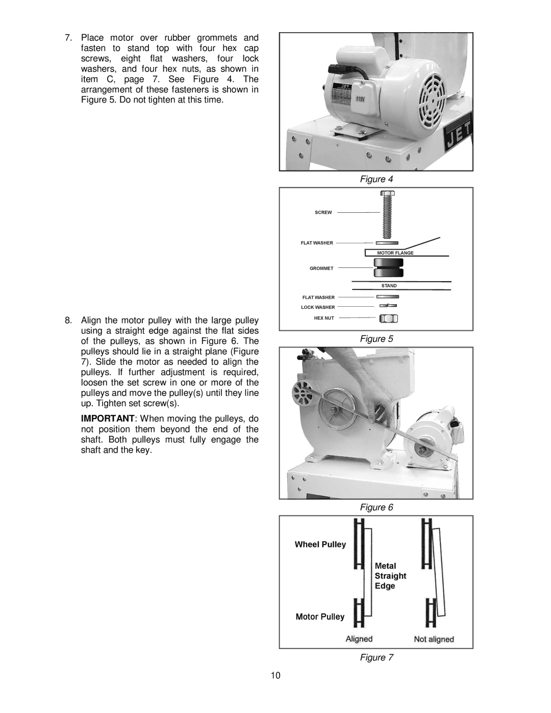
8.Align the motor pulley with the large pulley using a straight edge against the flat sides of the pulleys, as shown in Figure 6. The pulleys should lie in a straight plane (Figure 7). Slide the motor as needed to align the pulleys. If further adjustment is required, loosen the set screw in one or more of the pulleys and move the pulley(s) until they line up. Tighten set screw(s).
IMPORTANT: When moving the pulleys, do not position them beyond the end of the shaft. Both pulleys must fully engage the shaft and the key.
Figure 4
Figure 5
Figure 6
Figure 7
10